
ISBM Mould Design — Engineering the Preform, Blow Cavity, and Core Pin
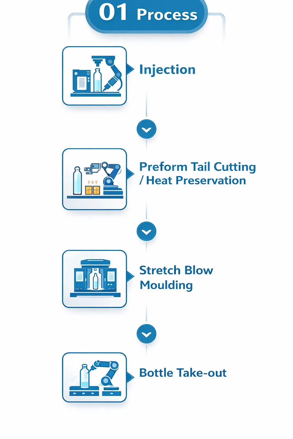
A well-designed ISBM mould is what separates a bottle that blows first time, every time from one that produces stress whitening, base pearlescence, wall thickness variation, or neck flash. The injection stretch blow moulding process integrates preform injection and bottle blowing in a single machine cycle — which means the preform mould and the blow cavity are not independent tooling decisions. They must be engineered together, matched to the same stretch ratio targets, and compatible with the same machine’s interface dimensions from the outset.
This guide covers the complete ISBM mould design process: preform geometry and wall thickness distribution, core pin tolerances and gate design, blow cavity surface finish and cooling channel layout, how to calculate and match stretch ratios between preform and cavity, the Aoki 100 and ASB-12M mould interface standards and what they mean for machine compatibility, what drives ISBM mould cost, and the information your supplier needs to conduct a mould feasibility review before steel is cut.
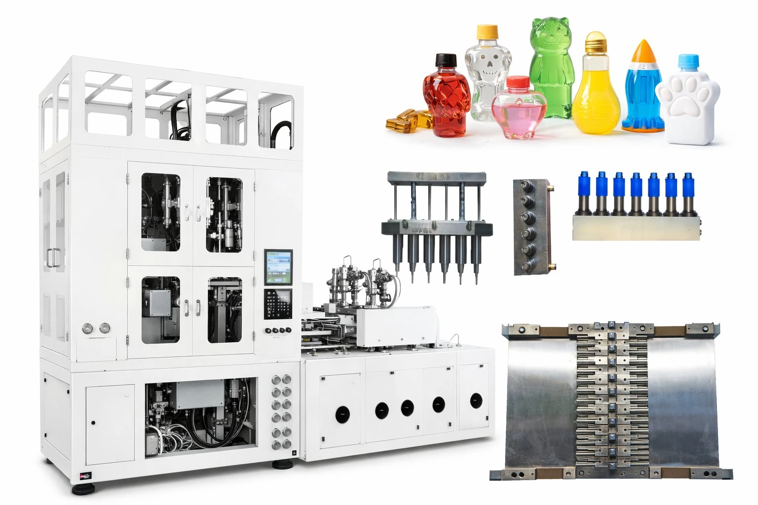
Why ISBM Mould Design Is Different from Standard Injection Moulding
In conventional injection moulding, the mould produces the final part. The designer optimises wall thickness, gate location, cooling layout, and draft angles to fill the cavity uniformly and eject a part that meets drawing. Success is measured by whether the part matches the drawing dimensions.
In ISBM mould design, the preform mould does not produce the final part — it produces a precursor geometry that will subsequently be stretched and blown into a completely different shape at the blow station. This changes every design decision:
- The preform’s wall thickness is not uniform — it is deliberately tapered to compensate for the non-uniform stretch ratios that occur at different heights of the blown bottle. A preform wall that is thicker at the base and thinner toward the shoulder will produce a blown bottle with more uniform wall distribution than a preform with equal wall thickness throughout.
- The neck finish is the only preform dimension that survives unchanged into the final bottle. Every other dimension is transformed by the stretch-blow cycle. The neck is formed in injection and locked by cooling before the preform reaches the blow station — making neck finish tooling the highest-precision element in the entire mould set.
- Preform mould and blow cavity must be matched as a system. A preform designed for a 3.0 ASR cannot be blown in a cavity designed for a 3.8 ASR without producing either understretch (poor orientation, thick walls, base pearlescence) or overstretch (stress whitening, shoulder splits). The two moulds are not interchangeable between machines or cavity configurations without re-engineering.
These constraints mean that ISBM tooling is a system engineering task, not simply two independent mould jobs. The most reliable approach is to have the preform mould and blow cavity designed and manufactured by the same supplier — or at minimum to have both designs reviewed together before any steel is committed.
Part 1 — Preform Mould Design
Preform Geometry — Wall Thickness Distribution
The preform’s wall thickness profile is the single most important design variable in ISBM tooling. The goal is to produce a blown bottle with wall thickness variation below ±0.05 mm — but the stretch ratio varies considerably across the height of the preform during blowing. The base stretches less than the body (the stretch rod exerts maximum force at the gate point); the shoulder stretches more than the body (the transition from preform body to the fixed neck finish concentrates stretch strain); and the body between gate and shoulder stretches at a rate proportional to the cavity geometry.
The designer must therefore pre-compensate by making the preform wall thicker where stretch ratio is lower (base and lower body) and thinner where stretch ratio is higher (shoulder and upper body). A common starting distribution for a standard cylindrical PET bottle is:
● Typical Preform Wall Thickness Distribution — Standard PET Bottle
Gate / base dome: thickest zone — 100–115% of nominal wall
Lower body: 95–105% of nominal wall
Mid-body: 90–100% of nominal wall (reference zone)
Upper body / shoulder approach: 80–90% of nominal wall
Neck support ring: returns to full thickness for structural support
The specific distribution is calculated from the blow cavity geometry and the target blown bottle wall thickness map. Every container design requires its own preform wall profile — generalised profiles are a starting point for trials, not a final design.
The most common preform design error is specifying uniform wall thickness to simplify tooling. A uniform-wall preform blown in a standard ISBM cavity produces a bottle with a thick, potentially pearlescent base, a thin and structurally weak shoulder, and a body that varies in wall thickness across its height — all consequences of applying a constant wall to a non-uniform stretch field. Correcting this defect on a finished tool requires costly steel addition or removal operations; it is far cheaper to design the wall profile correctly before cutting steel.
The Core Pin — Dimensional Accuracy and Cooling
The core pin defines the preform’s internal surface from gate to neck finish. Its outside diameter sets the preform’s inner diameter, and the annular gap between the core pin outside diameter and the cavity inside diameter defines the preform wall thickness at each height. Core pin dimensional accuracy directly determines preform wall uniformity — a core pin that is 0.02 mm eccentric to the cavity bore will produce a preform with a corresponding eccentricity in wall thickness that will amplify into a body wall asymmetry of 0.06–0.12 mm in the blown bottle.
Core pins are manufactured from through-hardened H13 or P20 tool steel, ground to tolerances of ±0.005 mm on diameter and straightness. The critical interface is the core pin / cavity alignment mechanism: ISBM preform moulds use precision-bored leader pins and bushing systems to maintain concentricity under the thermal cycling of production — a core pin that aligns correctly at room temperature but drifts under operating temperature differentials between the pin (cooled) and the cavity (heated) will produce progressive wall eccentricity across a shift.
Core pin cooling is typically internal: a water circuit runs through a central bore in the pin, providing chilled water contact with the inner surface of the preform gate dome. The gate dome is the thickest and hottest zone of the preform; adequate gate cooling is essential to achieving a cycle time that allows the gate to solidify before the mould opens. Insufficient gate cooling is a common cause of gate tearing on ejection — where the preform lifts off the core pin with a partially molten gate that tears and leaves material behind in the cavity.
Gate Design — Hot Runner for ISBM Preforms
Standard injection moulding uses cold runner systems with sprue gates or edge gates in many applications. ISBM preform moulds almost universally use hot runner systems with pin-point or valve gates at the preform base, for two reasons specific to ISBM:
- Cold runner elimination: ISBM preform moulds run on tight cycles (10–20 seconds); a cold runner would require additional cooling time to solidify before ejection and would produce significant material waste in a single-resin programme. Hot runners allow valve-gate closure at the end of injection, leaving no sprue to cool or trim.
- Gate vestige control: The preform gate vestige — the small protrusion left at the base by the pin-point gate — must be minimised and centred precisely on the preform axis. An off-centre or oversized gate vestige becomes the stretch rod contact point at the blow station, and any eccentricity in that contact initiates asymmetric axial stretch that produces an oval or off-centre bottle base. Valve-gate hot runners produce the smallest and most consistent gate vestige of any gate design.
Neck Finish Tooling — The Highest-Precision Element
The neck finish is the only dimension that passes unchanged from injection moulding to the final bottle. Every other bottle feature is shaped by the blow cycle; the neck is shaped entirely in the injection station and must be dimensionally correct to ±0.05 mm from the moment the mould opens. This makes the neck thread tooling — typically a split insert set that forms the external thread profile, tamper-evident bead, and support ledge — the highest-precision and most critically maintained element in the ISBM mould set.
Neck thread tooling is made from hardened steel (typically S136 or equivalent, HRC 50–54) with chrome plating on thread-forming surfaces to reduce wear in long-run production. The split line between the two neck insert halves must be positioned and polished to prevent a visible parting line mark on the thread that would impede cap or pump installation. Neck tooling must be replaced before thread profile wear reaches the tolerance limits for the cap or pump fitment specification — a worn neck thread that passes the bottle inspection gauge may still fail to achieve the torque specification on the filling line capper.
Part 2 — Blow Cavity Design
Cavity Surface — Polish, Texture, and Venting
The blow cavity surface finish transfers directly to the outside surface of the blown bottle. Because the bottle’s hot, plasticised wall is forced against the cavity surface at up to 3.5 MPa of blow pressure, it conforms to every surface detail — both intentional and accidental. This makes cavity surface selection and finish quality critical to achieving the intended bottle appearance.
Venting is equally critical to surface quality. As the bottle inflates against the cavity wall, air trapped between the bottle surface and the cavity must escape — otherwise it creates a surface defect called a “blow-back”: a localised dimple or mat area where the bottle contacted trapped air rather than the cavity surface. Vent slots are machined at the cavity parting line (0.01–0.02 mm deep, 1–2 mm wide) and at the base insert join. Insufficient venting is one of the most common causes of cosmetic surface defects on ISBM bottles, particularly in smooth-finish cavities for cosmetics where even a small vent-related defect is visible.
Cooling Channel Design — Cycle Time and Quality
Blow cavity cooling has a direct and quantifiable effect on both cycle time and bottle quality. The cavity wall must extract enough heat from the blown bottle during the blow-hold phase to drop the bottle wall temperature below PET’s Tg (~80 °C) before the cavity opens — if the wall is still above Tg when the mould opens, the bottle will deform and “shrink back” as the molecular chains relax from their oriented state. Inadequate cooling is therefore not merely an efficiency problem; it directly degrades the biaxial orientation quality in the finished bottle.
Cooling channel design best practice for ISBM blow cavities:
- Channel diameter: 8–12 mm, sized for turbulent flow (Reynolds number above 10,000) to maximise heat transfer coefficient. Turbulent flow in cooling channels transfers heat 3–5× more efficiently than laminar flow of the same channel cross-section.
- Channel spacing: typically 20–30 mm centre-to-centre, with channels following the contour of the cavity surface at a standoff of 8–15 mm. Channels closer than 8 mm risk stress cracking in the cavity wall; channels further than 20 mm from the surface create hot spots between channels.
- Conformal cooling — channels that follow the 3D contour of the cavity surface rather than running in straight lines — can reduce cycle time by 15–25% on complex bottle shapes (oval cross-sections, asymmetric shoulder profiles) by eliminating the hot spots that arise at corners and transitions in conventionally drilled straight-channel layouts.
- Base insert cooling: The bottle base requires more aggressive cooling than the body because the gate vestige area is the last to cool and the highest-temperature region at the start of the blow-hold phase. A separate cooled base insert with its own circuit is standard in production-grade ISBM cavity sets.
Draft Angles, Undercuts, and Mould Material
Draft angles on ISBM blow cavities are typically 0.5–2° per side on straight-walled body sections, increasing to 3–5° on the shoulder taper. Insufficient draft causes the bottle to bind in the cavity on opening, tearing the label area or distorting the neck finish. Undercuts — features that would lock the bottle in the cavity — require split inserts or collapsible core mechanisms; where possible, bottle designs should avoid undercuts below the neck support ledge.
Mould material selection determines tooling life and surface finish capability:
Beryllium copper is used selectively for cooling-critical inserts — particularly the blow cavity base insert and sometimes the core pin tip — because its thermal conductivity (105–120 W/m·K) is approximately 5× that of tool steel (15–25 W/m·K), enabling aggressive local cooling in zones where cycle time is constrained by heat extraction rate rather than by structural requirements.
Part 3 — Matching Preform to Blow Cavity
Matching the preform geometry to the blow cavity dimensions is the most critical calculation in ISBM tooling design. The two parameters that must be calculated and verified are the axial stretch ratio (ASR) and the hoop stretch ratio (HSR), each of which must fall within the target range for the resin being processed.
● Stretch Ratio Calculation Reference
Axial Stretch Ratio (ASR)
ASR = Hbottle ÷ Hpreform body
PET target: 2.5 – 4.0
PETG target: 2.0 – 3.5
Hoop Stretch Ratio (HSR)
HSR = Dbottle max ÷ Dpreform OD
PET target: 2.5 – 5.0
PETG target: 2.0 – 4.0
Overall Blow-Up Ratio (BUR) = ASR × HSR. For PET, the optimal BUR range is typically 8–16. Below 6, orientation is insufficient; above 20, overstretch defects become likely at standard processing temperatures.
Common Preform-to-Cavity Mismatch Problems and Fixes

Aoki 100 and ASB-12M Mould Standards — What They Mean
ISBM mould compatibility is not simply a matter of the mould fitting in the machine’s clamping area — it is defined by a precise set of interface dimensions that determine how the mould set locates, clamps, and transfers preforms within the machine’s rotary system. Two standards dominate the market for 3-station ISBM machines used in cosmetic, pharmaceutical, and specialty beverage production.
What the Standards Define
The ASB-12M and Aoki 100 mould standards specify a set of interface dimensions including:
- Cavity block width, height, and bolt pattern — defining where the blow cavity halves mount in the machine’s blowing station and how they are clamped
- Core pin pitch and diameter — defining the spacing between cavities and the diameter of the core pin interface, which must match the machine’s core pin holders
- Neck finish ring mounting interface — defining how the neck thread tooling locates relative to the preform cavity and the machine’s neck ring transfer mechanism
- Cooling water connection positions — specifying the inlet and outlet positions for cavity cooling circuits to match the machine’s cooling manifold
A mould built to the ASB-12M standard will physically install in any machine built to that standard — including machines from different manufacturers that have adopted the interface. The standard does not govern cavity geometry, bottle design, or process parameters, only the physical interface between mould and machine.
Why Mould Compatibility Is the Most Overlooked Machine-Buying Decision
Operations that have accumulated ISBM mould tooling over years of production — building a library of preform and blow cavity sets for their product range — have a significant tooling asset that must be considered when purchasing a new machine. A typical ISBM mould set costs a meaningful fraction of the machine price; an operation with 10–15 mould sets has a tooling library that may represent 40–60% of the value of the machine itself.
If a new machine uses a different mould standard from the existing tooling, the entire tooling library must be either rebuilt or adapted — at a cost that can equal or exceed the price differential between two machines. For this reason, mould standard compatibility should be identified as a hard requirement, not a preference, when specifying an ISBM machine purchase.
Which Standard for Which Korea Ever-Power Machine
Korea Ever-Power offers both interface standards in the HGY range. The HGY50-V3 and HGY50-V3-EV use the ASB-12M mould interface — the standard used by Nissei ASB machines widely deployed in Korean cosmetic and pharmaceutical factories. The HGY150-V3 uses the Aoki 100 mould interface — the standard used by Aoki Seiko machines, another platform with significant installed mould library in Korean and Southeast Asian ISBM operations. Operations with existing mould libraries on either standard can transfer their tooling to the corresponding Korea Ever-Power machine with minimal modification — confirmed at the mould drawing review stage before order placement.
ISBM Mould Cost — What Drives the Price
ISBM mould cost is consistently underestimated by buyers focusing only on machine price. For a complete project, the mould set typically represents 20–40% of the total investment — and that proportion rises toward 40% when the bottle design is complex (non-round cross-section, asymmetric shoulder, textured surface) or when multiple cavity configurations are required.
The primary cost drivers, in order of influence:
Cavity Count
Each additional cavity requires an additional complete preform mould insert, core pin, neck ring set, and blow cavity half pair. Tooling cost scales approximately linearly with cavity count — a 4-cavity tool costs roughly 3.5–3.8× a single-cavity tool (the base plate and manifold components are shared, but cavity-specific components are multiplied).
Bottle Geometry
Cylindrical bottles are the cheapest geometry — the cavity is a simple turned bore with a machined shoulder profile. Oval, rectangular, and asymmetric cross-sections require 5-axis milling of the cavity halves, increasing machining time and cost by 40–80% relative to cylindrical equivalents of the same volume.
Steel Grade and Surface Finish
S136 stainless steel with mirror polish for premium cosmetics costs 2–3× more than P20 pre-hardened with semi-gloss finish for standard beverage bottles of the same geometry. The additional cost is in both material (S136 is more expensive than P20 and harder to machine) and finishing labour (mirror polish requires multiple progressive polishing stages).
Neck Thread Complexity
Standard PCO 1881 or SP400 neck finishes are common-dimension thread forms that benefit from experienced toolmakers — their geometry is well-understood and efficiently produced. Non-standard neck thread profiles, tamper-evident features, or proprietary dispenser interfaces require custom thread ring design and qualified manufacturing, adding 15–30% to neck tooling cost per cavity.
Conformal Cooling
Blow cavity sets with conformal cooling channels (produced by metal additive manufacturing or wire EDM) cost 30–60% more than conventionally drilled cavity blocks of the same design. The cost premium is justified when cycle time reduction of 15–25% produces ROI within 6–12 months at the planned production volume — typically above 300,000 units per month per cavity.
3D Prototype Before Steel
Korea Ever-Power includes 3D prototyping in the mould feasibility process — a printed or cast prototype of the bottle geometry is produced from the CAD model and used to verify assembly fit, neck gauge acceptance, and label application before any steel is committed. The prototype cost is a small fraction of the tooling cost but eliminates the risk of discovering a design error after steel cutting.
Submitting a Bottle Design for ISBM Mould Feasibility Review
A mould feasibility review — also called a Design for Manufacturability (DFM) review — is the process by which the mould manufacturer evaluates the proposed bottle design before committing to tooling. It identifies design elements that would cause manufacturing problems, orientation defects, or structural failures in production, and recommends modifications that resolve those issues before any steel is cut.
The information required for a complete ISBM DFM review:
DFM Submission Checklist
✓ Bottle drawing (PDF + CAD, preferably STEP)
✓ Target bottle weight and wall gauge (g, mm)
✓ Resin type and grade (e.g., PET IV 0.76)
✓ Neck finish standard or custom drawing
✓ Required cavity count
✓ Target production rate (BPH)
✓ Surface finish requirement (gloss, matte, textured)
✓ Application type (cold-fill, hot-fill, pharmaceutical)
✓ Filling line closure type (cap, pump, dropper)
✓ Existing mould standard if applicable (ASB-12M / Aoki 100)
✓ Annual production volume estimate
✓ Delivery timeline requirement
Korea Ever-Power’s mould team typically returns a DFM report within 3–5 business days of receiving the complete submission package. The report includes: confirmation of the proposed preform wall thickness distribution, stretch ratio calculations, mould material recommendation, cavity count validation against the machine cycle time and target BPH, and any recommended bottle design modifications required for trouble-free production. Modifications identified at DFM stage cost nothing to implement; the same modification identified after steel cutting typically costs 15–25% of the original tooling price to correct.
◆ Key Takeaway
ISBM mould design is a system engineering task, not two independent tooling jobs. Preform wall thickness distribution, core pin concentricity, neck finish tooling precision, blow cavity cooling layout, stretch ratio matching, and mould standard compatibility must all be resolved before a single dimension is committed to steel. The cost of a correct design is the DFM review. The cost of an incorrect design is the full mould rebuild — plus the production and customer delays that come with it.
Conclusion
The ISBM mould set is the tooling that translates a bottle design into a manufactured product. Its preform geometry determines whether biaxial orientation is achieved consistently. Its blow cavity surface and cooling layout determine bottle appearance, clarity, and cycle time. Its stretch ratio matching determines structural performance. And its mould standard compatibility determines whether the tooling investment is protected when the machine is eventually upgraded or replaced.
For operations new to ISBM, or developing a new container format, the most important investment is in the DFM process — getting the preform design, stretch ratio calculations, and mould standard confirmed before steel is cut. Korea Ever-Power provides full mould design, DFM review, 3D prototyping, and mould manufacturing as part of its turnkey ISBM project offering across the HGY series 3-station ISBM range.

About this article: Prepared by the Korea Ever-Power Technical Team and Mould Design Department. Mould material selection data (hardness, expected shot life) is based on industry-standard ISBM tooling practice and Korea Ever-Power’s production mould performance records. Cooling channel design guidelines are based on published polymer processing engineering literature and Korea Ever-Power’s tooling design standards.
Related reading: What Is Injection Stretch Blow Moulding? — Process Guide | Biaxial Orientation in PET Bottles | How to Choose an ISBM Machine — 8 Specifications Explained | ISBM Machine Price Guide
Editor: Cxm