TECHNICAL DEEP-DIVE
Understanding Preform Design: The Foundation of Bottle Quality
Ninety percent of ISBM bottle defects originate at the preform stage — wall thickness variation, haze, thin corners, neck thread flash. Yet preform design is the least discussed topic in ISBM buying decisions. This guide walks through preform geometry fundamentals, stretch ratio calculation, gate placement, and the eight critical parameters our engineers verify on every bottle drawing before cutting mould steel.
In This Guide
- Why Preform Design Determines Everything
- Preform Geometry Fundamentals: Body, Neck, Gate
- The Stretch Ratio Calculation in Practice
- Wall Thickness Profiling and Uniformity
- Gate Design: Fan, Hot Tip, Valve Gate
- Neck Finish Standards
- Preform Weight Optimization
- 8 Critical Design Parameters Our Engineers Verify
- Case Study: 15ml Eye-Drop Preform for Korean Pharma
- Common Preform Design Mistakes to Avoid
- Conclusion and Next Steps
1. Why Preform Design Determines Everything
Ask any senior Korean production engineer with 10+ years on an ISBM line about the single biggest factor determining bottle quality, and the answer will always come back to the preform. Not the machine, not the operator, not the resin grade, not even the blow cavity polish. The preform. The small injection-moulded test-tube that enters the blowing station already carries within its geometry every strength, clarity, and dimensional outcome the finished bottle will ever achieve. Change nothing about the machine or the process, but change the preform, and you change everything downstream.
This reality is counterintuitive for Korean factory buyers who tend to focus their evaluation on machine specifications — injection clamping force, servo motor brands, PLC controllers. These specifications matter, but they determine upper performance bounds, not actual outcomes. The preform determines what actually happens within those bounds. An excellent preform on a mediocre machine still produces acceptable bottles; a poor preform on the world’s best machine still produces defective bottles. This is why custom ISBM mould design begins with preform engineering, and only after preform geometry is validated does steel cutting begin on the actual tooling.
Three categories of defects originate at the preform stage and cannot be fixed by any downstream adjustment. First, neck thread dimensional issues — because the neck finish is fully formed at injection and never reshaped during blowing, any tolerance problem here transfers directly to the finished bottle and breaks automated capping line compatibility. Second, wall thickness variation — because the stretch ratios during blowing depend on the starting preform wall profile, asymmetric preform walls produce asymmetric bottle walls regardless of how well the blow cavity is machined. Third, crystallization haze in the gate area — because the gate experiences the highest thermal stress during injection, improper gate design creates spherulitic crystals that appear as permanent cloudiness at the bottle base.
Over the past decade our engineering team has reviewed more than 400 new bottle projects from Korean cosmetic contract fillers, pharmaceutical packaging companies, and beverage bottlers. In roughly one-third of these projects, we identified preform design issues that would have caused production failures if the original specification had proceeded to tooling. Catching these issues before steel cutting saved each customer between $15,000 and $40,000 in avoided rework costs — which is precisely why the ISBM process engineering workflow we follow puts preform validation at the very first stage.
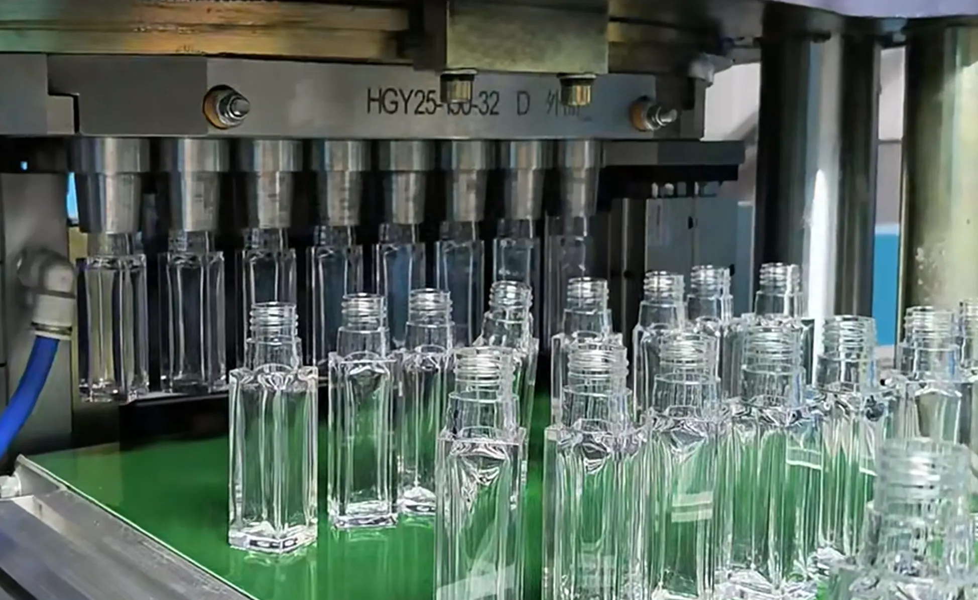
2. Preform Geometry Fundamentals: Body, Neck, Gate
Every ISBM preform has three distinct regions, each with its own design considerations and failure modes. Understanding how these three regions interact is the starting point for any preform specification conversation with your tooling supplier.
The Neck Finish
The neck finish is the top portion of the preform that contains the threaded closure interface. It is fully formed during injection and retains its exact geometry through blowing and into the finished bottle — no expansion or stretching occurs in this region. Because the neck finish is the final sealing interface for the bottle’s cap or pump dispenser, dimensional precision here is absolute. Korean automated capping lines in pharmaceutical and beverage facilities require neck thread tolerance within 0.02 mm to avoid capping rejects, and any variation beyond this tolerance cascades into filling line stoppages and rejected batches.
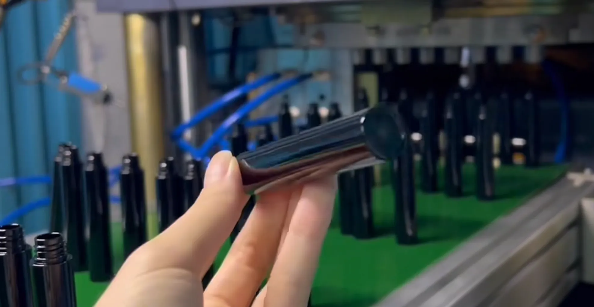
The Preform Body
The preform body is the cylindrical section below the neck that will stretch dramatically during blowing. This region’s starting dimensions determine the finished bottle dimensions through the stretch ratios we covered in the biaxial orientation article. For a typical 500 ml water bottle with 90 mm finished body diameter, the preform body outer diameter must be approximately 22 mm to deliver the required 4.1 hoop stretch ratio. Preform body length drives the axial stretch ratio: a finished bottle of 220 mm height requires roughly 95 mm preform body length for a 2.3 axial ratio.
The Gate and Base Dome
The gate is the injection point where molten resin enters the mould cavity, typically located at the center of the preform’s bottom dome. This is the hottest, most thermally stressed region during injection, and it is where crystallization defects most often originate. The base dome surrounding the gate must be thick enough to provide material for stretching but thin enough to avoid excessive heat retention that triggers spherulitic crystal formation. Our engineering team typically specifies base dome wall thickness between 3.0 and 4.5 mm for bottles in the 500 ml to 1.5 L range, with fillet radii generous enough to distribute thermal stress.

3. The Stretch Ratio Calculation in Practice
Every preform design starts with stretch ratio calculation. The math is straightforward: divide the finished bottle body diameter by the preform body outer diameter to get the hoop ratio; divide the finished bottle body height by the preform body length to get the axial ratio. For PET, target values are 4.0 to 4.5 for hoop and 2.5 to 3.0 for axial, as covered extensively in our biaxial orientation guide.
But knowing the target values is only half the work. The practical question is how to back-calculate preform dimensions from a target bottle. Here is the working methodology our engineering team applies to every new bottle project. Start with the finished bottle drawing and target resin weight. Divide the bottle body diameter by 4.2 (mid-range hoop ratio) to get the preform body outer diameter. Divide the bottle body height by 2.7 (mid-range axial ratio) to get the preform body length. Calculate preform wall thickness by dividing target bottle weight by preform volume with a 5 percent loss factor for gate and neck material not present in the final bottle. This initial specification gets validated through stretch-ratio simulation software before any steel cutting proceeds.
The table below shows typical preform dimensions for common Korean bottle formats, illustrating how the stretch ratio math drives preform geometry decisions. These are reference values; actual production preforms are tuned based on specific resin grade, bottle geometry complexity, and wall thickness requirements.
| Bottle Format | Preform OD (mm) | Preform Length (mm) | Wall Thickness (mm) | Weight (g) |
|---|---|---|---|---|
| 15 ml eye-drop | 12 | 32 | 1.8 | 3.2 |
| 150 ml cosmetic | 18 | 58 | 2.4 | 10.5 |
| 500 ml water bottle | 22 | 95 | 3.0 | 17 |
| 1 L beverage | 28 | 115 | 3.4 | 32 |
| 2 L large beverage | 34 | 140 | 3.6 | 48 |
| 5 L water gallon | 65 | 185 | 4.8 | 128 |
4. Wall Thickness Profiling and Uniformity
Preform wall thickness does not have to be uniform, and in fact should not be uniform for most bottle geometries. Different regions of the preform stretch to different ratios during blowing, so different starting wall thicknesses are required to end up with uniform wall thickness in the finished bottle. This is called wall thickness profiling, and getting it right is one of the highest-leverage decisions in preform engineering.
For a symmetric round bottle with straight walls, wall thickness profiling is relatively simple. Keep the body wall thickness constant along the preform length, and taper the wall slightly thicker toward the base dome to compensate for the higher stretch ratios that occur at the bottom where hoop expansion is greatest. For oval or asymmetric bottles — the shape most K-beauty cosmetic flacons take — profiling becomes substantially more complex. The preform must be thicker in regions that will stretch into sharp corners and thinner in regions that will stretch into flat panels, reversing the intuitive expectation about which preform regions correspond to which bottle features.
Finite element analysis (FEA) software is essential for wall thickness profiling on complex geometries. Our engineering team uses Moldflow and B-SIM to simulate the stretch pattern before cutting steel, predicting where the finished bottle will be thin, where it will be thick, and whether wall thickness uniformity meets the customer’s specification. For Korean premium cosmetic flacons with drop-test compliance at 1.5 meters, wall thickness must hold within ±10 percent variance across the entire bottle body, which requires iterative preform refinement over 2 to 3 simulation cycles before the design is finalized.
5. Gate Design: Fan, Hot Tip, Valve Gate
The gate is where molten resin enters the preform cavity during injection, and gate design drives three critical outcomes: fill balance across multi-cavity moulds, cycle time per shot, and risk of visible gate-area defects in the finished bottle. Three gate types dominate modern Korean ISBM production.
Hot Tip Gates
Hot tip gates are the most common design for PET preform moulds. A heated nozzle protrudes directly into the cavity base, delivering resin through a small orifice that seals off when the next shot begins. Hot tip gates produce a small, barely visible gate mark on the finished bottle base, which is acceptable for virtually all applications except premium optical clarity K-beauty packaging. Individual PID temperature control per nozzle on multi-cavity hot tip configurations allows Korean contract fillers to run 12-cavity and 16-cavity moulds with bottle-to-bottle weight consistency within 0.3 grams.
Valve Gates
Valve gates use a mechanical pin to open and close the gate orifice, eliminating the small gate mark entirely. The pin retracts during injection and advances to seal the gate at the end of the shot, producing a smoothly-cooled gate area with no visible witness mark. Valve gates cost substantially more than hot tip gates — typically 30 to 40 percent more per cavity on multi-cavity moulds — but they are essential for premium cosmetic applications where brand owners specify zero visible gate marks on the finished bottle.
Fan Gates
Fan gates spread the injection flow across a wider area of the cavity base, reducing local shear heating and crystallization risk. They are primarily used for heavy-wall preforms (5 L water gallons, large cosmetic jars) where gate-area thermal stress would otherwise cause base haze. Fan gates leave a more prominent witness mark than hot tips, so they are unsuitable for premium transparent packaging but well-suited to bulk applications where gate-area aesthetics are not commercially critical.
The choice between hot tip, valve gate, and fan gate is one of the first decisions our engineering team makes when designing a new mould. For most Korean projects in the 100 ml to 2 L range, hot tip is the default. For premium K-beauty applications in Ansan and Suwon contract filling operations, valve gate is increasingly the specification. For 5 L water gallon production in Gimhae and Busan, fan gate is the appropriate choice despite the visible gate witness.
6. Neck Finish Standards
The neck finish geometry follows industry-standard thread specifications that define thread pitch, number of thread starts, thread engagement depth, and support ring dimensions. Adhering to established standards is essential for compatibility with off-the-shelf closures — caps, pumps, trigger sprayers, dispensing valves — which avoids the enormous cost of custom closure tooling. The following standards dominate Korean and global ISBM production.
| Neck Standard | Typical Application | Thread Diameter (mm) |
|---|---|---|
| PCO 1881 | Carbonated beverages, water | 27.43 |
| 28-410 | Cosmetic lotions, pump dispensers | 28.00 |
| 24-410 | Small cosmetic bottles, serum | 24.00 |
| 24-415 | Pharmaceutical syrups | 24.00 |
| 38-400 | Juice, dairy, wide-mouth beverages | 38.00 |
| 48 mm | Sports nutrition, cosmetic jars | 48.00 |
| Wide-mouth 148 mm | Kimchi, gochujang, food jars | 148.00 |
For Korean pharmaceutical applications, the 24-415 specification is dominant because it supports child-proof and tamper-evident closures mandated by KFDA regulations. K-beauty cosmetic brands typically specify 24-410 or 28-410 depending on whether the product uses a dropper or pump dispenser. Beverage applications overwhelmingly use PCO 1881 (formerly PCO 1810), which is the global standard for water, soft drinks, and juice. Wide-mouth kimchi and food jars use custom 148 mm necks that require specialized heavy-duty ISBM machines like the BPET-125V4 Heavy-Duty 4-Station ISBM Machine with 685 KN injection clamping force.
7. Preform Weight Optimization and Lightweighting
The single largest economic lever in Korean bottle production is lightweighting. Because PET resin typically costs 1,400 to 1,700 KRW per kilogram and a typical Korean beverage bottler produces 10+ million bottles per year per SKU, reducing bottle weight by even 1 gram translates to 10,000 kg of resin saved annually, which is between 14 million and 17 million KRW direct material cost savings. Over the past decade, Korean brand owners have pushed for systematic lightweighting of standard bottle formats: 500 ml water bottles have dropped from 22 grams in 2010 to 13 to 15 grams today, a one-third reduction driven entirely by preform engineering.
Lightweighting is constrained by two physical limits. First, the total area stretch ratio must remain within the 10 to 13.5 optimal window to achieve biaxial orientation. Push beyond this window and the bottle develops pearlescent haze or fails drop testing. Second, wall thickness in critical stress regions — the bottle base, the neck transition zone, the label panel corners — must remain above roughly 0.25 mm to support top-load and drop-impact requirements. These constraints define the absolute minimum preform weight for any given bottle specification.
 |
 |
 |
 |
The practical lightweighting workflow starts with a baseline preform specification that produces reliably-passing bottles, then systematically reduces preform weight in 0.5 gram increments while monitoring drop-test compliance, top-load strength, and wall thickness variance. Typical optimization ends when further reduction causes drop-test failures or wall thickness drops below 0.25 mm in critical regions. Our engineering team provides this lightweighting service for Korean customers on every new project, typically finding 8 to 15 percent weight reduction opportunity versus the customer’s initial target specification.
8. 8 Critical Design Parameters Our Engineers Verify
Before any mould steel is cut, our engineering team verifies 8 critical preform design parameters against the customer’s target bottle specification. If any parameter falls outside acceptable ranges, we flag the issue and work with the customer to resolve it before proceeding to tooling manufacture.
- 1. Total area stretch ratio — Must fall within 10 to 13.5 for PET, 7 to 10 for PETG, adjusted for other resins per the orientation physics.
- 2. Individual axial and hoop ratios — Neither ratio should exceed the resin’s upper limit, even if the total area ratio is acceptable.
- 3. Wall thickness variance — Simulation must predict ±0.04 mm or tighter across the preform body length for optimal bottle uniformity.
- 4. Base dome thickness — Typically 1.2 to 1.5 times body wall thickness to handle higher stretch ratios without thinning.
- 5. Neck thread tolerance — Critical neck thread diameter must hold within 0.02 mm for automated capping line compatibility.
- 6. Gate location and type — Centered at the base dome with type (hot tip, valve, fan) matched to the bottle’s quality requirements.
- 7. Fillet radii at transitions — Minimum 2 mm radius at the neck-to-body transition to avoid stress concentration during blowing.
- 8. Cavity fill balance prediction — For multi-cavity tooling, Moldflow simulation must confirm ±2 percent fill balance across all cavities to ensure bottle-to-bottle consistency.
9. Case Study: 15ml Eye-Drop Preform for Korean Pharmaceutical Client
In early 2025 a Daejeon pharmaceutical contract manufacturer approached us to design tooling for a new 15ml eye-drop bottle on their existing ASB-12M platform. The client specified: 1×6 cavity configuration, 24-415 neck finish for child-proof KFDA-compliant closures, drop-test compliance at 1.2 meters, and target monthly production of 1.8 million bottles. The finished bottle body diameter was 22 mm and the height was 75 mm, giving a target volume of 15 ml with 3 ml overfill tolerance.
Working back from these specifications, our engineering team calculated the preform dimensions: 12 mm outer diameter, 32 mm body length, 1.8 mm wall thickness, 3.2 gram preform weight. Stretch ratios worked out to 1.83 axial and 1.83 hoop for a total area ratio of 3.35 — well below the typical PET optimal window. This is the reality of very small pharmaceutical vials: the stretch ratios are lower because the bottle is already quite small relative to the minimum practical preform size. To compensate, we specified a slightly warmer injection temperature and longer heat soak time on the ASB-12M thermal conditioning station to ensure adequate polymer chain alignment despite the lower stretch ratios.
The finished tooling corresponds to our Direct Replacement 15ml Core Mold for ASB-12M (1×6 Cavity) product, which ships with the hot runner base, cooling plates, and ejector fixing plate that our team designed for this specific customer project. Eight months into production, the facility reports bottle-to-bottle weight consistency within 0.08 grams, neck thread tolerance within 0.015 mm verified by Zeiss CMM, and zero drop-test failures in customer-side quality control inspections.

10. Common Preform Design Mistakes to Avoid
Over hundreds of Korean ISBM projects we see the same five preform design mistakes appear repeatedly, usually on projects where the customer or their original supplier skipped the stretch-ratio validation step. Here are the mistakes, what they cause, and how to avoid them.
Mistake 1: Over-Aggressive Lightweighting
Customers who specify preform weight below the physics-determined minimum produce bottles that pass first-article inspection but fail drop testing after 48-hour aging. The reason: over-stretched PET continues to crystallize for up to 72 hours post-production, gradually shifting optical and mechanical properties. Always validate drop-test performance on bottles aged at least 72 hours, not fresh off the line.
Mistake 2: Uniform Wall Thickness on Asymmetric Bottles
Designing a uniform-wall preform for an oval or asymmetric K-beauty bottle produces thin corners that fail drop testing. Always use FEA simulation to profile preform walls for non-round bottle geometries, accepting that the preform will look asymmetric but the finished bottle will be uniform.
Mistake 3: Ignoring Neck Transition Stress Concentration
Sharp transitions between the neck finish and the preform body create stress concentrations during blowing that cause neck cracking or thread distortion. Always specify minimum 2 mm fillet radius at the neck-to-body transition.
Mistake 4: Gate Type Mismatch
Using hot tip gates for premium K-beauty clarity applications produces visible gate marks that brand owners reject. Using valve gates for bulk water bottle production wastes 30 percent of the tooling budget on aesthetic benefits customers do not perceive. Match gate type to commercial requirements, not to default engineering preferences.
Mistake 5: Skipping Moldflow Simulation on Multi-Cavity Moulds
12-cavity and 16-cavity moulds cannot be designed by intuition alone. Without Moldflow simulation predicting fill balance, the outer cavities often receive insufficient melt while inner cavities over-fill, producing bottle-to-bottle weight variance of 0.8 grams or more. Always simulate before cutting steel on multi-cavity tooling.
11. Conclusion and Next Steps
Preform design is the invisible foundation of every successful ISBM production line. Korean factories that treat preform engineering as a throwaway upstream step — typically delegating the specification to their mould supplier without engineering review — experience the quality issues, reject rates, and drop-test failures that drain profitability over years of operation. Factories that invest in rigorous preform design upfront, with stretch-ratio calculation, wall thickness profiling, gate design matched to application, and 8-parameter verification before cutting steel, produce bottles that simply work from first-article through millions of subsequent cycles.
For Korean packaging buyers evaluating a new bottle project or troubleshooting quality issues on an existing line, preform engineering review is the single highest-leverage intervention available. Ever-Power’s engineering team provides this service as part of every custom mould design project, covering stretch-ratio simulation, Moldflow fill balance analysis, wall thickness FEA, and the full 8-parameter verification before any steel is machined. The service is included in our standard tooling pricing and typically adds 3 to 5 working days to the project timeline — a small investment against the 5 to 10 year operational lifespan of a well-designed mould.
If you are evaluating an ISBM mould purchase, planning a new bottle launch, or dealing with quality issues on an existing line, we would be happy to conduct a preform design review for your project. Share the target bottle drawing, resin specification, annual volume, and current or target production machine, and our Korean engineering team returns a preform specification with stretch-ratio validation and recommendations within 48 hours.
Key Takeaways
- 90% of ISBM bottle defects originate at the preform stage — this is where engineering investment pays off most.
- Preform has three critical regions: neck finish (never changes during blowing), body (stretches biaxially), gate/base (highest thermal stress).
- Stretch ratios are calculated by dividing finished bottle dimensions by preform dimensions; target 2.5-3.0 axial and 4.0-4.5 hoop for PET.
- Wall thickness profiling for asymmetric bottles requires FEA simulation; uniform preforms produce uneven bottles on non-round geometries.
- Gate type (hot tip, valve, fan) must match commercial requirements: hot tip for general use, valve gate for premium clarity, fan gate for heavy-wall applications.
- 8 critical parameters must be verified before cutting mould steel: area ratio, individual ratios, wall variance, base dome thickness, neck tolerance, gate design, fillet radii, fill balance.
Get Expert Preform Design Review for Your Bottle
Share your target bottle drawing, resin specification, and production volume. Our Korean engineering team returns a complete preform design proposal with stretch-ratio validation, wall thickness simulation, and fill balance prediction within 48 hours.
Editor: Cxm


