
เลือกหน้า

ISBM Machine Troubleshooting — 12 Common Blow Moulding Defects, Causes, and Fixes

Maintenance & Troubleshooting

Every ISBM machine operator encounters the same defects — often at the worst possible moment: at the start of a production run, in the middle of a shift, or when a customer’s quality team is due for an incoming inspection the next morning. The difference between an experienced process engineer and a novice operator is not that the engineer never sees these blow moulding defects — it is that the engineer knows immediately which parameter to change and by how much.

This ISBM machine troubleshooting guide addresses the most common PET bottle defects และ blow moulding problems and solutions encountered in daily production — including injection blow moulding defects that originate at the injection station, and blow-station defects that originate in conditioning or blow parameter settings. It is organised by the symptom the operator observes in the finished bottle, not by the machine component that is involved. Each defect has a structured entry covering: what the defect looks like, which root causes produce it, which one to check first (the most likely cause), and the specific parameter adjustment or maintenance action that resolves it. A quick-reference table at the top allows experienced operators to locate defects rapidly; the detailed entries below provide the full diagnostic context for each.

Quick Reference — 12 ISBM Defects at a Glance
# ข้อบกพร่อง Most Likely Root Cause Check First Process Stage
1 ความหนาของผนังไม่สม่ำเสมอ Non-uniform preform conditioning temperature Conditioning station barrel/core temperature balance Conditioning
2 Bottle haze Conditioning temp too low (PETG) or too high (PET crystallisation) Conditioning temp setpoint vs actual; cavity venting Conditioning / Blow
3 Flash at parting line Insufficient blow clamping force Blow clamp pressure; mould parting line condition Blow
4 Short shot (incomplete preform) Insufficient injection pressure or shot volume Shot weight actual vs setpoint; resin moisture การฉีด
5 Stress whitening / crazing Stretch ratio exceeds material limit Conditioning temp (raise 2–3 °C); stretch rod speed (reduce 10%) Blow
6 Bubble / void in preform Inadequate resin drying; moisture in melt Dryer temp and dew point; resin lot moisture spec การฉีด
7 Base pearlescence / halo Insufficient axial stretch at gate zone Gate zone conditioning temp (+2–3 °C); stretch rod position Conditioning / Blow
8 Neck finish dimensional drift Inadequate neck cooling; mould wear Neck ring cooling water flow; neck ring gauge dimensions Injection / Conditioning
9 Hot-fill bottle deformation Insufficient heat-set dwell time or mould temperature Blow mould temperature (raise to 120–150 °C); dwell time (min 2 s) Blow (heat-set)
10 Take-out / ejection failure Ejection timing or gripper wear Mould open stroke; blow station dwell end timing Blow / Take-out
11 Yellowing (Tritan / PC) Barrel temperature above setpoint; excessive residence time All barrel zone actual temps vs setpoint; purge frequency การฉีด
12 Inconsistent cycle time Hydraulic pressure fluctuation; conditioning temp drift Hydraulic oil temperature; conditioning fluid temp stability All stages

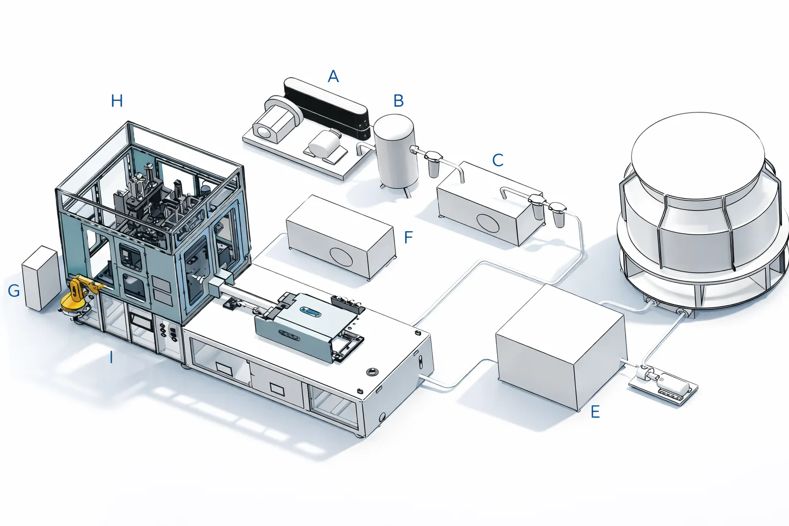
ISBM machine troubleshooting — production line layout showing injection station conditioning station blow station for PET blow moulding defect diagnosis
Figure 1 — The three-station ISBM production layout. Most blow moulding defects originate at a specific station — understanding which station governs which defect symptom is the first step in efficient troubleshooting. Defects visible in the preform (bubbles, short shot, yellowing) originate at the injection station. Defects in the blown bottle body (haze, uneven wall, stress whitening, pearlescence) originate at the conditioning or blow station. Defects in the neck finish originate at the injection or conditioning station.

How to Use This Guide

Observe the defect in the bottle or preform → locate the defect number in the quick-reference table → read the “Check First” column for the most likely cause → jump to the detailed entry below for root cause analysis and specific parameter corrections. If the first correction does not resolve the defect, work through the secondary causes listed in the detailed entry. For a deeper understanding of how the ISBM process produces quality bottles, see our guide to what is injection stretch blow moulding.

Defect 1 — Uneven Wall Thickness

SymptomWall thickness measured at the same height varies by more than ±0.08 mm around the bottle circumference. The thicker side is visible as a more translucent zone; the thinner side may show stress whitening in extreme cases.
สาเหตุที่เป็นไปได้มากที่สุดThe conditioning station barrel temperature is not uniform around the preform circumference — one side is warmer and stretches more during blowing, producing a thinner wall. Core pin eccentricity is the second most common cause.

Diagnosis and Fix: Check the conditioning station barrel temperature at four angular positions (0°, 90°, 180°, 270°) using a contact pyrometer on the preform surface immediately before the blow station. A temperature difference of more than 3–5 °C between positions indicates a conditioning barrel problem — either uneven heating element output, poor barrel-to-preform contact, or a fluid flow restriction in one zone of the barrel circuit. Balance the barrel temperature by adjusting zone setpoints until circumferential variation is below 2 °C. If the temperature is uniform but wall thickness is still asymmetric, check core pin concentricity: remove a preform before blowing and measure wall thickness at four points with a caliper — if the preform itself is eccentric, the core pin or cavity alignment is the root cause, requiring tooling inspection.

Defect 2 — Bottle Haze (Loss of Clarity)

SymptomThe blown bottle is milky, cloudy, or has localised haze patches in the body or base. Haze values measured above 2% on an instrument, or visible clouding under direct light. PETG haze typically appears as a uniform cloudiness; PET haze may be localised at the base or shoulder.
Root Causes — Check in Order(1) Conditioning temperature too low for PETG (below 88 °C body zone) → preform enters blow station underheated, stretches unevenly, develops strain-induced crystallinity → haze. (2) Conditioning temperature too high for PET (above 120 °C) → strain crystallisation during blow → haze. (3) Insufficient cavity venting → trapped air between bottle wall and cavity surface produces blow-back marks that appear as localised mat haze. (4) Mould cooling water too warm (> 18 °C) → bottle wall above Tจี when mould opens → surface distortion, apparent haze.

Fix by resin: For PETG, raise the conditioning barrel setpoint by 3–5 °C and verify the actual preform body temperature reaches 92–96 °C before the blow station. For PET haze at the base, lower the gate zone conditioning temperature by 3 °C (the base is typically the last zone to cool and can over-crystallise). For blow-back mat marks, deepen parting-line vent slots to 0.02 mm and add vent pins at affected zones. For mould cooling issues, reduce cooling water supply temperature to 8–12 °C and verify flow rate.

Defect 3 — Flash at the Parting Line

SymptomA thin fin of PET material protrudes from the bottle body along the blow mould parting line. Flash can range from a barely-visible edge (0.05 mm) to a significant structural protrusion that prevents label application and fails bottle gauge inspection.
Root Causes(1) Blow clamping force below the minimum required to hold the mould closed against blow pressure — the most common cause. (2) Parting line surface damaged or worn — allowing material to extrude into the gap even with sufficient clamping. (3) Blow pressure set above the mould’s rated maximum. (4) Mould not seating fully — foreign material or deformed mould mounting preventing full closure.

Fix: First, verify the blow clamp pressure on the machine gauge against the specification for the installed mould (typically 60–100 kN for standard ISBM blow moulds). If pressure is correct, inspect the parting line faces of both cavity halves for damage — a nick or raised burr on either face will prevent full sealing regardless of clamping force. Parting line damage requires re-polishing or re-grinding the affected face by a toolmaker. If both clamp and parting line are correct, check that the mould is seating fully in the blow station by measuring the gap between mould blocks with a feeler gauge at four points on a manually clamped (no blow pressure) cycle.

Defect 4 — Short Shot (Incomplete Preform Fill)

SymptomThe preform is visibly under-filled — the gate dome is thinner than specified, the body wall is thinner than normal, or in severe cases, the preform has a partially open end at the gate. Short shots in multi-cavity tools may affect one or more cavities while others fill correctly.
Root Causes(1) Shot volume (screw cushion position) set below the required value — check if screw is bottoming out before the cavity fills. (2) Injection pressure insufficient to overcome melt viscosity — common after a resin lot change if the new lot has higher IV. (3) Resin moisture above 0.004% — hydrolytic chain scission reduces melt viscosity and makes the melt flash through vents rather than filling the cavity. (4) In multi-cavity tools: hot runner imbalance directing melt preferentially to certain cavities.

Fix: Weigh preforms from the affected cavity and compare to the specification. If all cavities are light, increase injection volume (screw recovery position) by 2–3 mm and recheck. If one cavity is consistently light in a multi-cavity tool, check the hot runner balance: measure individual cavity gate temperatures with an infrared pyrometer and equalise within ±2 °C. For a resin moisture problem, verify the hopper dryer outlet dew point (should be below −40 °C) and material temperature (65 °C for PET, 80 °C for Tritan). After correcting moisture, purge 3–5 shots before accepting production.
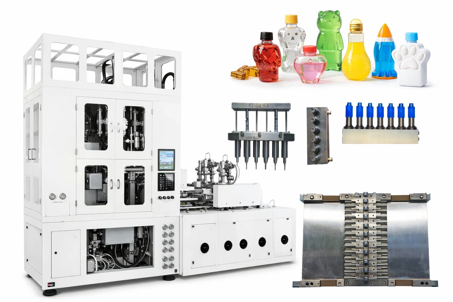
ISBM blow mould tooling — parting line flash defect mould cavity inspection troubleshooting PET bottle defects
Figure 2 — ISBM mould tooling. Defects 3, 5, 7, and 8 all have a mould-related root cause — parting line condition, cavity surface venting, gate dome geometry, or neck ring wear — that requires physical inspection of the tooling rather than a machine parameter change. When parameter adjustments fail to resolve a defect, inspect the tooling as the next diagnostic step before assuming the machine is the cause.

Defect 5 — Stress Whitening (Crazing)

SymptomWhite or opaque streaks or patches in the bottle wall, typically at the shoulder, upper body, or base dome. In severe cases, the white areas have a crazing pattern (fine surface cracks). The defect appears immediately upon blowing and does not improve on standing.
Root CausesStretch ratio in the affected zone has exceeded the material’s orientation limit — the chains have been pulled beyond the strain-hardening point and have fractured rather than aligning. This produces microvoids that scatter light. Causes: (1) Preform temperature too low — material is too cold and brittle during blowing. (2) Stretch rod speed too high — material fractures before it can orient. (3) Preform wall too thin in the affected zone — insufficient material to distribute the stretch.

Fix: The correction priority is temperature first. Raise the conditioning station setpoint for the body zone by 3–5 °C (PET: target 108–112 °C; PETG: 93–97 °C) and produce a trial batch. If stress whitening persists but is reduced, continue raising temperature in 2 °C increments until it disappears. If temperature adjustment does not help, reduce stretch rod speed by 10–15% — a slower rod descent gives the preform more time to deform plastically rather than fracturing. If stress whitening only occurs at the shoulder, the preform’s upper body wall may be too thin; the mould DFM should be reviewed with the toolmaker.

Defect 6 — Bubbles or Voids in the Preform Wall

SymptomVisible bubbles, voids, or splay marks in the preform wall. Bubbles appear as spherical inclusions; splay marks appear as silver or grey streaks following the melt flow direction. Both survive into the blown bottle and are visible as inclusions or surface marks.
Root Causes(1) Resin moisture above the specified limit — water vapour in the melt produces bubbles during injection. (2) Barrel temperature too high — thermal degradation of the polymer produces volatile decomposition products that form bubbles. (3) Injection speed too fast — air entrapment from poorly vented hot runner or gate. (4) Screw back-pressure too low — inadequate melt homogenisation before injection.

Fix: Bubbles and splay are almost always a moisture problem. Immediately check: (a) hopper dryer setpoint is at the correct temperature for the resin (65 °C for PET, 80 °C for Tritan, 120 °C for PC); (b) drying time has been met (minimum 4 hours for all resins); (c) the desiccant in the dryer is not saturated — confirm outlet dew point is below −40 °C with a dew point meter, not by assuming. If moisture is confirmed as the cause, extend the drying time to 6 hours before next production run. If drying conditions are correct and bubbles persist, reduce barrel zone temperatures by 5 °C across all zones and check for degraded material in the screw flights by performing a purge.

Defect 7 — Base Pearlescence (Halo Effect)

SymptomA white, pearly, or hazy ring around the gate dome of the blown bottle — visible as a “halo” at the base centre. The defect is caused by spherulitic crystallisation at the gate area, which scatters light and creates the white appearance. In severe cases, the entire base dome is white.
Root CausesThe gate zone of the preform is not reaching orientation temperature before blowing — it enters the blow station too cold (or with insufficient heat penetration through the wall thickness at the gate dome, which is the thickest zone). The stretch rod does not orient the gate dome sufficiently, and the unoriented material crystallises on contact with the cool cavity wall. The gate dome is the most difficult zone to condition because it is the thickest, farthest from the conditioning barrel surface, and furthest along the heat transfer path from the core.

Fix: Raise the gate zone conditioning temperature by 3–5 °C above the body zone setpoint (not the body zone — the gate zone specifically, which has its own setpoint on dual-zone conditioning systems). Additionally, verify that the stretch rod is reaching its full travel position — if the rod stops short of the gate dome contact point, the gate zone receives no mechanical stretch and will always pearl regardless of conditioning temperature. Confirm rod travel with a measurement check at the blow station with the mould closed but no blow pressure. If the base pearlescence persists after temperature and rod travel corrections, the preform’s gate dome wall thickness may be insufficient for adequate heat penetration — review the preform design with the mould supplier.

Defect 8 — Neck Finish Dimensional Drift

SymptomThe neck finish (thread OD, neck ID, or height from support ledge) is drifting out of specification — typically discovered during a gauge check, a closure fitment test, or a pump application torque test. The drift may be progressive across a shift (increasing as the machine warms up) or random (varying shot to shot).
Root Causes(1) Neck cooling water flow restricted — the neck ring requires continuous chilled water cooling to maintain dimensional stability; if flow is reduced, the neck exits the mould above Tจี and distorts on ejection. (2) Neck ring wear — thread profile worn below gauge by accumulated shot cycles, typically on high-volume programmes. (3) Conditioning station passing heat to the neck zone — if the conditioning barrel contacts the neck finish, it can raise the neck temperature above Tจี, causing distortion.

Fix: First, check the neck cooling water flow at the mould outlet — it should be flowing at 2–4 L/min at 8–15 °C. A restricted or partially blocked neck cooling circuit is the most common cause of progressive neck drift across a shift, because the neck ring temperature rises slowly as mould cycling heats the tooling and the restricted circuit cannot extract heat fast enough. If flow is correct, gauge the neck ring tooling: use a calibrated thread gauge and neck OD gauge to check whether the tooling dimensions are within tolerance. Neck ring replacement is the correction for worn tooling — there is no process adjustment that compensates for a neck ring that is below its minimum gauge dimension.
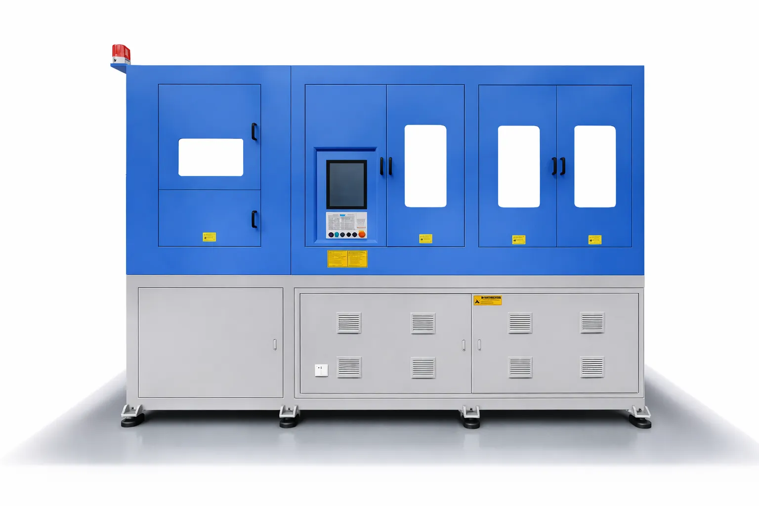
ISBM machine blow moulding troubleshooting — machine parameter adjustment for PET bottle defects cycle time inconsistency hydraulic pressure
Figure 3 — Most ISBM defects are resolved by parameter adjustment on the machine controller rather than by tooling intervention. The rule is: start with the most likely process parameter cause, make one change at a time, and verify the effect on the next 20–30 bottles before making a second change. Making multiple simultaneous parameter changes makes it impossible to identify which change resolved the defect — or which one made it worse.

Defect 9 — Hot-Fill Bottle Deformation After Filling

SymptomBottles deform permanently when filled with liquid at 88–95 °C — the body collapses inward, the base inverts, or the neck deflects under closure torque. The deformation may be visible immediately on the filling line or may develop as the bottle cools from hot-fill temperature.
Root Causes(1) Heat-set dwell time too short — below 2 seconds, insufficient crystallinity develops (less than 20%) to stabilise the bottle wall above PET’s Tจี. (2) Blow mould temperature too low — if the oil heater setpoint is below 120 °C, the heat-set rate is inadequate regardless of dwell time. (3) Standard cold-fill machine used for hot-fill — standard HGS-A machines lack the stretching stroke and oil-heated mould circuit for hot-fill production. (4) Resin IV too low for hot-fill — IV below 0.78 dl/g does not develop sufficient crystallinity at standard heat-set conditions.

Fix: First, confirm the blow mould oil heater is maintaining 120–150 °C at the mould inlet. If the mould temperature is correct, extend the heat-set dwell time from its current value to at least 2.5 seconds and re-run a trial batch. Measure wall crystallinity by DSC (differential scanning calorimetry) — it should be 20–30% in the bottle body wall after heat-setting. If crystallinity is below 20% with correct mould temperature and dwell time, the resin IV is likely the problem — switch to a hot-fill grade resin with IV 0.80–0.85 dl/g. Note that if a standard HGS-A model is being used instead of the HGS200B, the stretching stroke may be insufficient to achieve the axial orientation depth required for hot-fill crystallinity regardless of all other parameters — this is not a process parameter problem, it is a machine specification mismatch.

Defect 10 — Take-Out / Ejection Failure

SymptomBottles stick in the blow cavity and do not eject reliably — they remain in the mould when it opens, fall during take-out, or are deformed by the take-out mechanism. The machine may alarm on ejection failure and stop production.
Root Causes(1) Mould open stroke too small — the cavity halves do not open far enough to clear the bottle body; common after a bottle height change without checking the mould open stroke setting. (2) Bottle not cooled sufficiently before ejection — mould cooling circuit restricted, allowing the bottle to remain above Tจี when the mould opens; the soft bottle deforms on ejection. (3) Blow station dwell time too short — the mould opens before the pressure has released, causing the bottle to be ejected while under internal pressure. (4) Draft angles insufficient on mould cavity — the bottle grips the cavity surface and will not release without a force that damages it.

Fix: Check the mould open stroke programmed value against the bottle body height plus 20 mm minimum clearance. If the stroke is correct, measure the bottle surface temperature on ejection — it should be below 60 °C for standard PET (below Tจี). A surface temperature above 65 °C indicates insufficient cooling; reduce cooling water temperature or extend the mould close time. If the problem occurs intermittently, it may be the exhaust valve timing — the blow pressure must be fully exhausted before the mould opens; check that the exhaust valve opens and closes at the correct positions in the cycle.

Defect 11 — Yellowing in Tritan or PC Bottles

SymptomPreforms or blown bottles have a yellow or amber tint — ranging from a very slight warm cast (detectable only against a white background) to a pronounced yellow that is immediately visible at normal inspection. The yellow tint is uniform across the body in barrel-temperature yellowing; it may be concentrated at the gate dome in localised overheating or extended residence time.
Root Causes(1) Barrel temperature above setpoint in one or more zones — the most common cause; even 5–8 °C above the Tritan target of 260–285 °C initiates visible yellowing. (2) Excessive melt residence time — during production stops or slow cycles, material degrades in the barrel. (3) Purging failure at shutdown — if the barrel is not purged before shutdown, the residual Tritan or PC in the barrel degrades overnight and produces yellow-tinged material for the first 10–20 shots of the next run. (4) Contamination from previous resin — residual PET or PETG from the previous production run can cause discolouration with Tritan at its processing temperature.

Fix: Check every barrel zone actual temperature against its setpoint on the HMI. A zone running 5 °C or more above setpoint indicates a failed or malfunctioning heater control — check the thermocouple, the PID controller output, and the heater element continuity. If all zones are within setpoint, investigate residence time: count the number of machine cycles during the last production stop longer than 5 minutes and compare to the typical purge cycle — for Tritan, any stop longer than 10 minutes at processing temperature requires a purge of 3–5 shots before production resumes. For shutdown, establish a written SOP requiring a full barrel purge with a neutral PET grade before every scheduled shutdown. For start-up after an overnight stop on Tritan, purge 8–10 shots before accepting production and check the colour of the purge material against the specification colour standard.

Defect 12 — Inconsistent Cycle Time

SymptomThe machine cycle time varies from shot to shot — observed as irregular machine sounds, inconsistent BPH output, or HMI alarm on cycle time overrun. Cycle time variation of more than ±0.5 seconds on a 15–20 second cycle is operationally significant and causes downstream production problems (preform queue buildups, thermal variation in the conditioning station).
Root Causes(1) Hydraulic oil temperature outside operating range — cold oil (below 35 °C) is more viscous and slows all hydraulic actuators; hot oil (above 55 °C) is less viscous and may cause pressure regulation instability. (2) Conditioning station temperature drift — if the preform is under-conditioned on some cycles, it resists the stretch rod and extends the blow cycle. (3) Injection screw recovery time variable — indicating a feeding or plastication issue (bridging in hopper, worn screw flight, back-pressure inconsistency). (4) Compressed air supply pressure dropping below 3.0 MPa — the blow cycle extends as pressure ramps more slowly.

Fix: For hydraulic machines, monitor the hydraulic oil temperature gauge and confirm it is in the 40–50 °C operating range before accepting production. If oil temperature is low at start-up, run the machine in manual cycle mode (no injection) for 10–15 minutes to warm the oil before starting a production run. For a fully electric machine — which does not use hydraulic oil — cycle time variation is almost always due to conditioning temperature drift or injection screw recovery time. Monitor the injection screw recovery time on the HMI: it should be consistent within ±0.2 seconds per cycle; if it varies more, check the hopper for bridging, verify back-pressure setpoint has not changed, and inspect the screw for wear if the problem is persistent. The HGY50-V3-EV fully electric machine eliminates hydraulic oil temperature as a variable entirely — servo motor response is consistent from cold start, making cycle time stability significantly easier to maintain in multi-shift production.

Korea Ever-Power ISBM machine quality certification — systematic troubleshooting and quality control for PET blow moulding defect prevention
Figure 4 — Systematic quality control — including first-article inspection, in-process gauging, and machine parameter logging — prevents most of the 12 defects in this guide from reaching a full production batch. Prevention is always cheaper than rejection: a 30-second dimensional check at the start of each production run or mould change catches most defects before they affect the batch, not after.

◆ Key Troubleshooting Principle

ทั้งหมด blow moulding defect has a process-stage origin: if the defect is in the preform (bubbles, short shot, yellowing), look at injection. If the defect is in the blown bottle body (haze, stress whitening, wall variation, pearlescence), look at conditioning and blow station parameters. If the defect is in the neck finish, look at injection cooling and neck ring condition. Make one change at a time, produce 20–30 bottles between changes, and record what changed and what the result was. A troubleshooting log across shifts is more valuable than any individual fix — patterns that are invisible in a single production run become obvious over a week of systematic records.

บทสรุป

The 12 blow moulding defects in this guide account for the large majority of quality issues experienced on ISBM production lines. Most are resolvable with parameter adjustments that take minutes; a smaller number require tooling inspection or replacement that takes hours. The most important discipline for an ISBM operator is the habit of checking one variable at a time, in the order of most-likely to least-likely cause, and recording the result before moving to the next check. Experienced process engineers solve these problems quickly not because they know magic solutions, but because they have a systematic approach and a record of what works.

บริษัท โคเรีย เอเวอร์-พาวเวอร์ HGY series 3-station ISBM machines are supplied with full commissioning support and process documentation that establishes the baseline parameters for each container programme — giving operators a documented starting point for troubleshooting rather than relying on informal knowledge transfer. Contact Korea Ever-Power’s technical support team for application-specific defect diagnosis assistance on installed machines.

เกี่ยวกับบทความนี้: Prepared by the Korea Ever-Power Technical Team based on field service records, commissioning reports, and process engineering experience across HGY and HGS series installations. Temperature targets and parameter ranges are guidelines for standard bottle-grade PET and PETG; specific resins, preform designs, and cavity configurations may require different setpoints established during commissioning.

บทความที่เกี่ยวข้อง: Biaxial Orientation in PET Bottles — How ISBM Achieves It  |  ISBM Mould Design — Preform, Blow Cavity, and Core Pin  |  What Is Injection Stretch Blow Moulding? — Process Guide

บรรณาธิการ: Cxm

ทัวร์เสมือนจริงชมโรงงานของเรา

แท็ก: