ISBM Mould Change Procedure — How to Switch Cavities in Under 30 Minutes
Maintenance & Troubleshooting
A fast, reliable ISBM mould change is one of the most commercially valuable skills in a multi-SKU blow moulding operation. Every minute spent on a blow moulding mould changeover is a minute the machine is not producing — and at 350–500 bottles per hour, the cost of a slow changeover accumulates quickly. An operation running five mould changes per week that takes 90 minutes each loses approximately 37 hours of production per month; the same operation with a trained team completing each change in 25 minutes loses just over 10 hours. The 27-hour difference is real production capacity that either earns revenue or eliminates overtime.
This guide provides the complete ISBM mould changeover procedure — covering how to change a mould on an ISBM machine from safe stop through first-article acceptance — in eight steps with time targets per step. It also includes blow moulding quick mould change tips built into the preparation checklist and parallel-working sequence, a description of the four most costly changeover mistakes and their specific consequences, realistic time benchmarks by operator experience level, and mould storage practices that prevent tooling degradation between production runs. For operations seeking an ISBM quick mould change capability — consistently under 30 minutes — the preparation checklist and Step 6 stretch rod verification are the two most impactful practices to implement first.
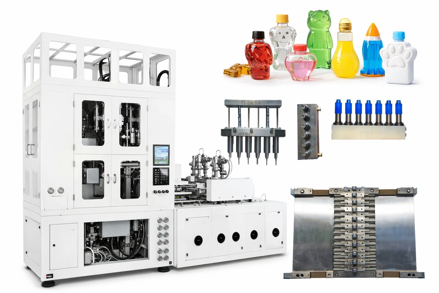
Figure 1 — A complete ISBM mould set: blow cavity halves (left pair), preform injection mould with core pins (centre), and neck ring set (right). An ISBM mould change involves replacing all three tooling groups in a defined sequence, with parameter updates to the machine controller between each physical installation step. Understanding which hardware changes before which parameter update — and why — is the foundation of a fast, defect-free changeover.
Why Mould Changeover Time Matters for Production Economics
For an operation running a single bottle format on a dedicated machine, mould changeover time is largely irrelevant — the machine runs the same programme for weeks or months between changes. For a multi-SKU cosmetic, pharmaceutical, or food packaging operation — the typical profile of an เครื่อง ISBM in Korea — mould changeovers happen weekly or even daily, and their cumulative effect on monthly output is significant.
37 hrs
Lost per month
5 changeovers/week × 90 min each — slow, unorganised team
17 hrs
Lost per month
5 changeovers/week × 40 min each — trained operator, some preparation
10 hrs
Lost per month
5 changeovers/week × 25 min each — disciplined procedure, pre-staged tooling
At 400 bottles per hour on a standard cosmetic container programme, those 27 additional hours saved by a well-disciplined changeover procedure represent approximately 10,800 bottles of additional monthly output — without any additional machine investment. The mould changeover procedure is the highest-return process improvement available to a multi-SKU operation, ahead of maintenance schedule compliance, resin cost optimisation, and cycle time tuning.
Before You Start — Preparation Checklist
The most common source of long changeover times is not slow physical work — it is the time wasted searching for a tool that was not pre-staged, waiting for a mould that was not pre-warmed, or discovering that the new programme’s parameter file was not loaded before the machine was shut down for the change. All of this time is avoidable by completing the preparation checklist before production stops on the outgoing programme.
● Pre-Changeover Preparation Checklist — Complete Before Stopping Production
✓ New mould set physically located and confirmed correct (check mould ID label vs job traveller)
✓ New mould set pre-warmed to 40–50 °C in the mould warming cabinet (30 min minimum before install)
✓ New programme recipe file confirmed loaded on HMI — do not rely on operator memory for parameter entry
✓ Cooling water supply valves to both stations confirmed closed and tagged out
✓ Blow station exhaust valve confirmed closed; compressed air supply isolated at machine inlet valve
✓ Stretch rod end-of-travel position for new mould noted from recipe card (critical — do not look this up mid-changeover)
✓ Conditioning station new zone profile temperatures noted from recipe card
✓ First-article inspection gauges for new container confirmed at operator station (neck OD gauge, wall thickness gauge)
✓ Outgoing mould storage location confirmed clear and labelled — do not allow outgoing tooling to be set on floor during changeover
8-Step Mould Change Procedure
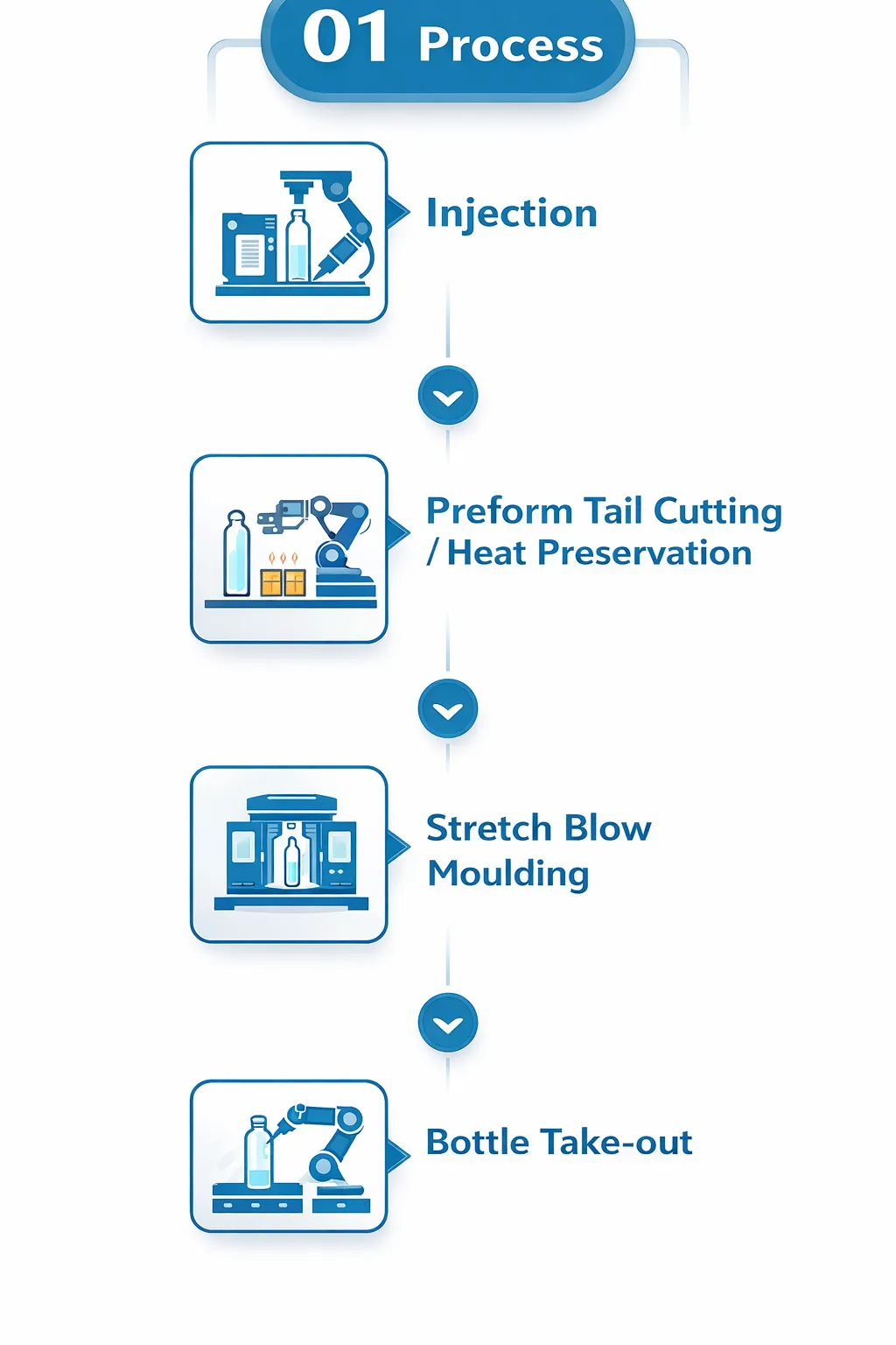
The steps below are sequenced to minimise total changeover time by parallelising where possible and sequencing temperature-sensitive steps so that wait times are used productively. Each step has a time target for a trained single operator; a two-person team achieves some steps faster where parallel working is possible.
Figure 2 — The three-station ISBM layout determines the changeover sequence. Work on the blow station (Step 2) can be performed while the injection station barrel is cooling (Step 1), because the barrel must cool before the core pins can be safely removed. Sequencing these steps in parallel — rather than waiting for the barrel to cool before touching the blow station — is the single most effective time-saving technique in a well-run ISBM mould change.
1 Cool Down and Safe Stop Target: 5 min active
Complete the last production cycle. On the HMI, select Mould Change Mode (or Stop if the machine does not have a dedicated mode) — this prevents automatic cycling while work is in progress. Set all barrel temperature zone setpoints to 150 °C to begin controlled cool-down; do not switch heaters fully off (thermal shock from rapid cooling accelerates barrel zone heater element fatigue). Purge the barrel by injecting forward three times with the nozzle open to expel residual melt — this clears the hot runner and nozzle tip and prevents residual pressure in the injection unit. Isolate: close compressed air supply valve at machine inlet, close cooling water supply to injection station, tag out main power isolator if company lockout/tagout procedure requires it for mould work.
Wait time during cool-down: use this time to complete Steps 2 (blow station) and 3 (conditioning station) while the barrel temperature drops. Do not remove injection core pins until barrel is below 80 °C — typically 15–20 minutes from cool-down initiation.
2 Remove Blow Cavity Halves Target: 5–7 min
With compressed air isolated and blow station confirmed exhausted (no pressure), disconnect the cooling water hoses from both cavity halves using quick-disconnect fittings — confirm no water flow before disconnecting. Loosen the cavity clamping bolts in the sequence specified in the mould data card (typically diagonal sequence to release clamping pressure evenly). Using the mould handling tool or two-person lift as appropriate for mould weight, remove both cavity halves and place immediately on the pre-labelled mould trolley or storage rack — never on the machine bed or floor. Wipe the blow station platen faces with a clean cloth to remove cooling water residue and inspect for any damage to the alignment pin bores.
3 Remove Preform Mould Core Pins and Neck Ring Target: 5–8 min (after cool-down)
Only proceed once barrel temperature is below 80 °C. Confirm with the barrel zone temperature display — do not estimate by touch. Disconnect injection mould cooling hoses. Remove the neck ring set first (the most thermally sensitive component — it must be removed before the cavity to avoid neck ring distortion from residual heat). Unscrew core pin retention bolts in the specified sequence; withdraw core pins from the heated runner plate using the core pin extraction tool. Place all components in the outgoing mould set’s labelled storage tray — core pins, cavity halves, neck rings, and hot runner nozzle tip together. Do not allow core pins to contact each other during storage; use the foam-lined tray supplied with the mould set.
4 Install New Preform Mould Core Pins and Neck Ring Target: 5–7 min
Install the new core pins into the runner plate following the specified torque value (typically 15–25 Nm depending on core pin size — always torque to specification, never by feel; under-torqued core pins back out under injection pressure and cause short shots). Install neck ring: confirm the neck ring ID matches the new preform’s neck specification using the calibrated thread gauge before installing — do not assume the correct ring is in the tray. Torque neck ring retention bolts to specification. Connect injection mould cooling hoses and verify flow at the outlet connection before proceeding.
5 Install New Blow Cavity Halves Target: 5–7 min
Insert the new blow cavity alignment pins into the blow station platen. Position cavity half A onto the alignment pins first; do not tighten. Position cavity half B; bring the two halves into contact manually and verify that the parting line mates cleanly — no gap, no misalignment step. Tighten the clamping bolts to the specified torque in the diagonal sequence. Connect cooling hoses to both halves; verify flow at outlets. Check that the cavity is seated squarely on the platen faces — an off-square cavity will produce flash at one end of the parting line on the first blow cycle.
6 Set Stretch Rod Travel and Blow Clamp Parameters ★ Critical Target: 3–5 min
This is the most critical parameter step in the entire changeover. The stretch rod must travel to within 1–2 mm of the gate dome of the new preform — not the previous preform. A stretch rod set to the previous mould’s travel position will either stop short (producing base pearlescence and poor orientation) or over-travel into the new mould’s gate dome (producing a hole in the preform base — an immediate reject and possible rod damage).
Procedure: on the HMI, load the new mould programme recipe. Verify the stretch rod end-of-travel position value against the value recorded on the mould’s recipe card. If loading a recipe from the HMI library, confirm the recipe name includes the mould serial number — not just the bottle name, as the same bottle may have been produced on multiple mould versions with different travel settings. In manual mode, cycle the stretch rod through one stroke without blow pressure applied and confirm it reaches the programmed end position without resistance.
Do not proceed to Step 7 without verifying stretch rod travel in manual mode. This verification takes 30 seconds and prevents the most common first-article defect after a changeover.
7 Set Conditioning Station Zone Profile for New Preform Target: 3–5 min + 10–15 min stabilisation
The conditioning station barrel and core temperature profile must be set for the new preform’s wall thickness and length — not carried over from the previous programme. Even a minor difference in preform wall gauge (0.2 mm) or preform length (5 mm) requires a different conditioning temperature profile to achieve the same preform surface temperature at the blow station entry. If the new recipe is loaded from the HMI library (strongly recommended over manual entry), confirm all temperature zone values match the recipe card before starting the stabilisation period. Increase all barrel zones to the new setpoints and allow 10–15 minutes for full stabilisation before attempting the first production cycle.
Stabilisation time: use this wait period to verify barrel temperature zones are reading within ±2 °C of setpoint, to prepare the first-article inspection gauges, and to stage the new resin lot on the hopper if a resin change is part of this changeover.
8 First Article Inspection — Accept or Adjust Target: 5–8 min
Run the first five production cycles and retain all bottles. Inspect the first five bottles against the acceptance criteria before declaring the changeover complete and starting a production count: (1) neck OD within ±0.05 mm of specification using the go/no-go gauge; (2) body wall thickness at three heights within ±0.05 mm of specification; (3) no visual defects — no haze, no stress whitening, no flash at parting line, no base pearlescence; (4) bottle weight within ±0.3 g of specification. If any criterion fails, refer to the relevant defect entry in the ISBM machine troubleshooting guide before adjusting parameters. Accept production only after five consecutive good bottles. Record the first-article results in the changeover log.
Four Common Changeover Mistakes — and Their Specific Consequences
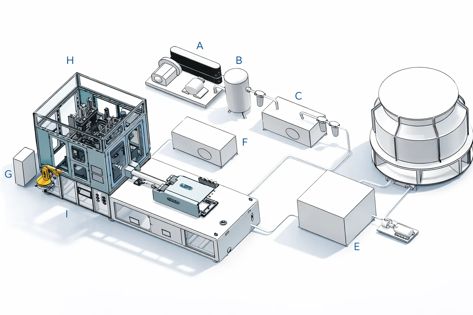
Figure 3 — Production line view during ISBM changeover. The most costly changeover mistakes are invisible during the physical installation steps — they only manifest when the machine starts producing, at which point discovering them requires stopping production again, identifying the cause, and losing additional time. Prevention through systematic parameter verification (Step 6 and Step 7) is far faster than diagnosis after the fact.
⚠ Mistake 1 — Not Updating the Stretch Rod Travel Position
ผลที่ตามมา: If the new preform is taller than the previous one and the rod travel is not extended, the rod stops short of the gate dome — producing base pearlescence and under-oriented bottle bases that fail top-load testing. If the new preform is shorter and travel is not reduced, the rod tip contacts the gate dome before full extension — in extreme cases, punching a hole through the preform base and potentially damaging the rod tip. Either failure is only discovered on the first production cycle, after all other changeover work is complete — costing 5–15 minutes of additional downtime while the problem is diagnosed and corrected.
⚠ Mistake 2 — Carrying Over the Previous Programme’s Conditioning Temperature Profile
ผลที่ตามมา: A preform with a different wall gauge or length than the previous programme will not reach the correct orientation temperature under the same conditioning zone settings. A thicker preform under-conditioned produces stress whitening in the bottle body and poor clarity. An over-conditioned thinner preform produces blow-through at the shoulder (a hole in the bottle body) or stress marks from overcooling on a PETG programme. In either case, the first-article inspection fails and the operator must adjust conditioning temperatures and wait another 10–15 minutes for re-stabilisation — effectively adding a full stabilisation cycle to the changeover time.
⚠ Mistake 3 — Installing the Wrong Neck Ring
ผลที่ตามมา: Neck rings for different container formats are often visually similar — the OD difference between a 20/410 and 24/410 neck ring is 4 mm, which is not immediately obvious without measurement. Installing the wrong neck ring produces preforms with the wrong neck thread profile. These preforms will blow into bottles that pass visual inspection but fail the closure fitment test — discovered at incoming inspection by the customer, not during production. The entire batch produced before discovery is a reject. Prevent by gauging the neck ring with a thread gauge before installation — not after.
⚠ Mistake 4 — Accepting Production Before Five Consecutive Good Bottles
ผลที่ตามมา: The first one or two bottles after changeover are frequently acceptable — the machine is in a transition period where residual heat from the previous programme’s conditioning station cycle is still influencing the first few preforms. Bottles 3–8 are the ones that reveal whether the new programme is stable. Accepting production based on the first two bottles and starting a count produces a batch that begins with quality bottles and deteriorates as the old thermal state dissipates — yielding a mixed-quality batch that is difficult to sort and may require full inspection by the customer.
Time Benchmarks — What Is Achievable at Each Experience Level
The following benchmarks reflect the actual changeover times recorded across Korea Ever-Power HGY series installations. They assume proper pre-changeover preparation (checklist complete before machine stops) and a single trained operator — the two-person team times in the final column reflect parallel working on Steps 2–5.
Experience Level
Changeover Time (1 person)
Changeover Time (2 person)
ปัจจัยจำกัด
First changeover (no prior training)
90–120 นาที
60–80 min
Unfamiliarity with tool locations, torque sequences, and parameter update sequence; multiple re-checks
Best practice — pre-warmed mould, recipe pre-loaded, 2-person team
—
< 20 min
Conditioning stabilisation wait; achievable with pre-warmed mould (40–50 °C) which shortens temperature recovery
The 10–15 minute conditioning stabilisation period in Step 7 is effectively the floor of achievable changeover time — it is physically unavoidable because the conditioning station cannot reach and stabilise at a new temperature faster than the thermal mass of the system permits. Pre-warming the new mould to 40–50 °C in a mould warming cabinet before installation reduces this period slightly but does not eliminate it. The correct management approach is to use this wait period productively (first-article gauge staging, documentation, preform staging) rather than to attempt to shorten it by starting the machine before the conditioning temperature has stabilised.
Mould Storage Best Practices
Figure 4 — Mould storage area requirements: temperature-controlled to below 25 °C, relative humidity below 60%, with dedicated shelving that holds moulds horizontally on their parting line (not vertically, which risks cavity face contact damage). Each mould set’s tray includes the mould itself, all core pins, neck rings, and the recipe card — everything needed to install and run the mould without searching for missing components.
A mould that is stored incorrectly between production runs arrives at the next changeover in degraded condition — corroded parting line faces, seized bolt threads, or a core pin that has a rust spot in the cavity zone that will transfer to every preform it makes. Proper mould storage takes five minutes at the end of a changeover and saves significant time and quality loss at the next installation.
● Mould Storage Requirements — After Each Production Run
✓ Allow cavity halves to cool fully to below 35 °C before applying rust inhibitor — applying to a hot surface causes the inhibitor to volatilise rather than coat
✓ Apply a light coat of cavity-grade rust inhibitor (not WD-40, which leaves a residue that contaminates the next production run) to all cavity faces, core pin surfaces, and neck ring bores
✓ Wipe parting line faces clean and inspect for nicks or raised burrs before storage — mark any damage on the mould condition card for attention before next installation
✓ Store all components of one mould set together in the labelled tray: cavity halves, core pins, neck rings, hot runner nozzle tip, bolt kit, and recipe card
✓ Store trays horizontally on dedicated shelving — never stack cavity halves face-to-face, which causes cavity surface contact damage
✓ Storage area: below 25 °C, relative humidity below 60%; in humid climates (Southeast Asian facilities), use desiccant sachets in storage trays and replace monthly
✓ Update mould condition log: date of last use, production cycles run, any quality issues or repairs performed
✓ For moulds out of service for more than 3 months: apply heavier-grade storage compound, wrap in VCI (Vapour Corrosion Inhibitor) film, and seal tray
◆ ข้อสรุปสำคัญ
A fast, defect-free ISBM mould change is not a talent — it is a procedure. The 8-step process above, combined with the pre-changeover preparation checklist and the four mistake-prevention rules, consistently produces first-article-pass changeovers in 25–35 minutes for a trained single operator. The 10-minute conditioning stabilisation period is unavoidable; everything else is within the team’s control. Invest one hour in training the procedure correctly on the first changeover, and every subsequent changeover benefits for the machine’s entire service life.
บทสรุป
The ISBM mould changeover is a repeatable procedure that improves with practice and degrades with shortcuts. Operations that treat it as a structured process — pre-staging tooling, loading recipes before stopping the machine, verifying stretch rod travel before first production, and completing proper mould storage at each change — consistently achieve 25–35 minute changeovers and near-zero first-article reject rates. Operations that treat it as an ad hoc task run by whoever is available when the change is needed consistently spend 60–90 minutes and produce their first defective batch after the changeover, not their last.
The complete preventive ISBM machine maintenance schedule — including weekly and monthly mould-related maintenance tasks — works in parallel with a good changeover procedure to keep tooling in consistently good condition. Korea Ever-Power provides machine-specific mould change procedure documentation with each HGY series machine delivery. Contact Korea Ever-Power’s technical support team for application-specific changeover optimisation guidance on your installed machine and mould combination.
เกี่ยวกับบทความนี้: Prepared by the Korea Ever-Power Technical Team. Changeover times reflect field data from HGY series machine installations with trained operators and proper preparation; individual results vary by operator experience, facility layout, and mould design. Torque values and specific parameter settings referenced as “recipe card” values are machine- and mould-specific — consult the machine-specific maintenance manual and mould data card for the correct values for your installation.
บทความที่เกี่ยวข้อง: ISBM Machine Maintenance Schedule — How to Achieve 95% Uptime | ISBM Machine Troubleshooting — 12 Common Defects | ISBM Mould Design — Preform, Blow Cavity, and Core Pin