
ISBM Machine Maintenance Schedule — How to Achieve 95% Uptime
Korea Ever-Power Technical Team
|
Reading time: approx. 18 min
|
Updated 2026
A well-maintained ISBM machine runs at 93–97% planned uptime across a production year. A neglected machine runs at 75–85% — and the 10–20% difference is not experienced as a slow, gradual decline but as a series of unplanned stops: a hydraulic seal that fails mid-shift, a conditioning station thermocouple that drifts and produces an hour of out-of-specification bottles before the operator notices, a screw that has been running undersized for months and is now producing short shots. The cost of these unplanned stops — in lost production, quality rejects, and emergency repair labour — consistently exceeds the cost of the preventive maintenance programme that would have prevented them.
This guide provides a complete ISBM machine maintenance schedule — equally applicable as a blow moulding machine maintenance programme for any injection stretch blow moulding platform — structured by interval. It covers daily shift-start checks (the essential blow moulding machine daily maintenance checklist), weekly and monthly maintenance, 500-hour and 2,000-hour service, annual overhaul, the specific differences in injection blow moulding machine maintenance between hydraulic and electric drives, screw and barrel care (the most consequential ISBM screw barrel maintenance decisions), and how to maintain an injection stretch blow moulding machine through a documented log that proves the programme was followed. Operators asking how to maintain an injection stretch blow moulding machine or what a complete PET bottle machine maintenance programme covers will find a complete answer in this guide, structured for direct implementation.
It also covers the specific maintenance differences between hydraulic and fully electric drive machines, screw and barrel care, purging procedures between resin changes, and a maintenance log template that gives maintenance teams a documented basis for warranty claims and machine life management. Understanding how to maintain an injection stretch blow moulding machine properly starts with recognising that different machine systems degrade at different rates — and that the maintenance schedule must address each at its appropriate interval.

Why ISBM Maintenance Matters More Than Two-Step Machines
An ISBM machine integrates three production processes — injection moulding, temperature conditioning, and stretch blow moulding — in a single machine and a single cycle. This integration is the source of the process’s quality advantages; it is also the reason why maintenance is more consequential than on a two-step machine where the same three processes are separate.
In a two-step REHB line, a fault on the preform injection machine stops preform supply but does not immediately stop the blow moulding machine — the buffer of preforms in gaylord storage provides operating time while the injection machine is repaired. On an ISBM machine, there is no buffer. A fault at any station — injection, conditioning, or blow — stops the entire machine and production ceases immediately. This makes the ISBM machine’s overall availability equivalent to the product of the individual station availabilities: if each station is 98% available, the machine’s combined availability is approximately 94% (0.98 × 0.98 × 0.98). Preventive maintenance’s goal is to keep each station above 99% planned availability, yielding a combined machine availability above 97%.
Additionally, on a two-step machine, a quality problem in the injection station (producing substandard preforms) affects only the bottles blown from those preforms — which can be caught by inspection before blowing if an in-line preform inspection system is fitted. On an ISBM machine, a conditioning station drift that produces an out-of-specification preform temperature is reflected immediately and directly in the blown bottle quality, with no opportunity for interception between the stations. This is why the conditioning station temperature sensors — the most common drift-prone component in the conditioning system — must be checked and calibrated on a regular schedule, not just replaced when they obviously fail.
Daily Checks — Every Shift Start (15 Minutes)
The daily shift-start check is the most important element of the maintenance programme — not because it is the most technically complex, but because it is the check that catches the overnight drift, the slow leak, and the developing abnormality before they become a production stoppage. Every operator should complete these checks before starting the production cycle and record the results in the maintenance log.
● Daily Shift-Start Checklist
✓ Hydraulic oil level (sight glass) — top up if below min mark
✓ Hydraulic oil temperature — confirm 40–50 °C before cycling
✓ Cooling water supply temperature — should be 8–15 °C
✓ Cooling water flow at all mould circuits — confirm flow at each outlet
✓ Compressed air supply pressure — should be ≥ 3.2 MPa (safety margin above 3.0 MPa operating)
✓ Hopper dryer temperature and dew point — confirm setpoint reached and dew point ≤ −40 °C
✓ Conditioning station barrel and core temperature — all zones within ±2 °C of setpoint
✓ Lubrication points — apply grease to tie-bar, toggle pins, and rotary table bearings per lubrication chart
✓ Barrel and nozzle temperature — confirm all zones within ±3 °C of setpoint before first injection
✓ First-article inspection — weigh first 5 preforms; measure first 3 blown bottles (wall thickness, neck OD)
✓ Visible leaks check — hydraulic, cooling water, compressed air — around all fittings and actuators
✓ Safety guarding — all guards in position; emergency stop function verified
The first-article inspection step is the most frequently skipped and the most valuable. Measuring three bottles at the start of a shift (wall thickness at 5 heights + neck OD) takes 4 minutes and catches parameter drift from the previous shift — barrel temperature that settled overnight, cooling water temperature that rose after the weekend — before it affects an entire batch. An operation that performs first-article inspections consistently will almost never produce a full batch of out-of-specification bottles; one that does not will regularly discover quality problems at the end of the batch during outgoing inspection.
Weekly Maintenance (2–3 Hours)
Weekly maintenance is most efficiently performed at the end of the last production shift of the week, while the machine is warm and hydraulic systems are at operating temperature — conditions that make it easier to identify slow leaks, check actuator stroke consistency, and verify that fluid circuits are flowing correctly.
● Weekly Maintenance Checklist
✓ Hydraulic filter condition indicator — replace if red/pressure drop indicated
✓ Cooling water strainer — remove and clean all circuit strainers (25-mesh minimum)
✓ Electrical cabinet — blow out accumulated dust with dry compressed air; check door seal
✓ Compressed air filter-regulator — drain water from bowl; check element condition
✓ Blow station stretch rod — inspect for straightness; check tip condition; measure total travel
✓ Mould clamping mechanism — check guide pin and bushing for wear; verify clamping symmetry
✓ Barrel nozzle — inspect for drool or freeze; check nozzle tip thread engagement
✓ Conditioning station fluid circuits — verify both barrel and core flows; check hose fittings for weep
✓ Rotary table indexing — check index time consistency over 10 cycles; listen for bearing noise
✓ Control panel — check for alarm history since last weekly check; clear only after cause identified
Monthly Maintenance (4–6 Hours)
Monthly maintenance requires a planned production downtime window — not a gap opportunistically exploited between production runs, but a scheduled stop with spare parts on hand and maintenance personnel allocated. The tasks at this interval require partial disassembly of several machine components and are not safe or practical to perform while the machine is in production mode.
● Monthly Maintenance Checklist
✓ Barrel thermocouple calibration — verify each zone thermocouple actual vs calibrated reference; replace if drift > 3 °C
✓ Conditioning station thermocouple calibration — same procedure for all conditioning zones
✓ Hydraulic system pressure — verify main circuit, injection circuit, and clamping circuit pressures against specification
✓ Toggle mechanism lubrication — grease all toggle pins, bushings, and sliding surfaces per lubrication chart
✓ Stretch rod straightness — verify with dial indicator over full travel; replace if runout exceeds 0.1 mm
✓ Blow valve function — cycle each valve manually; verify open/close response time within specification
✓ Neck ring cooling circuit — remove neck ring set; clean cooling channels; verify flow rate before reinstall
✓ Conditioning barrel contact check — verify barrel makes even contact with preform surface at all clock positions
✓ Hydraulic oil sample — draw 100 ml sample for viscosity and contamination check; compare to new oil specification
✓ All cable and hose routing — check for chafe or wear against machine frame; re-route or protect if contact found
The barrel and conditioning thermocouple calibration step is the most commonly deferred task in this list — and the one with the highest quality impact when neglected. A thermocouple that reads 3 °C below actual temperature will cause the PID controller to drive the heater harder, resulting in a barrel zone that runs 3 °C above the operator’s setpoint. For Tritan production, this margin is the difference between acceptable and visibly yellow bottles. Thermocouple calibration takes 10 minutes per zone using a portable calibration reference and the machine’s own digital temperature display — it is a simple verification that pays for itself on the first shift of Tritan production where it prevents a quality batch failure.
Every 500 Operating Hours
Five hundred hours of machine running time corresponds to approximately 10–12 weeks of single-shift production, or 5–6 weeks of double-shift production. The 500-hour service interval addresses wear items that degrade too slowly to detect on a weekly or monthly inspection but accumulate to a consequential level over this period:
Every 2,000 Operating Hours
Two thousand hours corresponds to approximately one year of single-shift production or six months of double-shift production. This is the interval at which major system components that degrade below the threshold of routine inspection require planned replacement or rebuilding:
Hydraulic Oil Change
Drain and replace all hydraulic oil (ISO VG 46 anti-wear grade, or as specified in the machine manual). Flush the system with new oil for one full cycle before draining and filling with fresh oil. At the oil change, also replace the high-pressure filter element and clean the oil tank interior. Oil oxidation above 2,000 hours produces varnish deposits on valve spools that cause slow or intermittent valve response — the root cause of cycle time inconsistency in hydraulic machines at this age.
Servo Motor and Drive Inspection (Electric Machines)
For fully electric machines, the 2,000-hour service includes: checking servo motor winding insulation resistance (should be above 10 MΩ at 500V DC); inspecting coupling between servo motor and ball screw for wear or play; verifying ball screw backlash by measuring screw end-float (should be below 0.05 mm); cleaning ventilation filters on all servo amplifier units.
Full Accuracy Verification
At 2,000 hours, the machine’s geometric accuracy should be verified against its commissioning record: rotary table indexing repeatability (±0.1 mm), injection station platen parallelism (±0.05 mm), blow station platen parallelism, and stretch rod alignment to cavity centre. Any dimension outside tolerance requires mechanical correction before the machine returns to production — operating with out-of-alignment platens produces progressive mould wear that accelerates tooling cost.
Annual Overhaul
The annual overhaul is a planned shutdown of 3–5 days during which the machine is partially disassembled for inspection, cleaning, and preventive parts replacement. It is best scheduled during a planned production gap — the holiday season, a product changeover period, or a quarter with naturally lower demand — to minimise the impact on production schedules. Key annual overhaul scope items:
- Barrel and screw removal: The screw is fully withdrawn from the barrel for visual inspection of flight wear along its entire length, and the barrel bore is inspected with a bore gauge and a calibrated bore scope for erosion, corrosion, or damage. Screw clearance to barrel bore is measured at 5 positions; any measurement above 0.20 mm indicates the screw flight tips have worn and the screw should be replaced before wear reaches the barrel bore itself (barrel replacement costs 3–5× more than screw replacement).
- Mould set inspection: All installed moulds are removed, disassembled to component level, cleaned (including cavity surfaces, cooling channels, and parting line faces), and dimensionally verified. Cavity surface polish is inspected and re-polished where worn. Neck ring dimensions are verified against the bottle specification gauge. Cooling channel internal surfaces are pressure-flushed with a mild acidic cleaner to remove scale deposits that reduce heat transfer.
- Rotary table bearing inspection: The rotary table is lifted and the central bearing raceway is inspected for brinelling, spalling, or corrosion. The table index mechanism is disassembled, cleaned, and reassembled with fresh grease. Indexing repeatability is re-verified against the commissioning specification.
- Electrical system inspection: All terminal connections are checked for tightness; loose terminals are the leading cause of intermittent electrical faults. Contactor contacts are inspected for pitting or burning; worn contacts are replaced. All thermocouple and sensor cables are inspected for insulation damage, particularly near hot zones where the insulation degrades over time.
Hydraulic vs Electric Drive — Different Maintenance Focus
The maintenance burden is not equal between hydraulic and fully electric machines. The difference is not in total maintenance hours per year — both machines require approximately the same total maintenance time over a 2,000-hour cycle — but in what the maintenance addresses and how much of it requires specialist hydraulic knowledge versus general mechanical and electrical competence.
The HGY50-V3-EV fully electric machine reduces annual maintenance hours by approximately 30–35% relative to the hydraulic V3 — primarily by eliminating the hydraulic oil management tasks (daily level checks, oil sampling, filter replacement, oil change at 2,000 hours, and seal replacement at 500-hour intervals). This reduction in maintenance burden is partially offset by the additional requirement for servo motor insulation testing and ball screw backlash verification that the electric machine introduces. On balance, the electric machine is significantly simpler to maintain for operators without specialist hydraulic knowledge — which is the typical staffing profile of small and mid-size ISBM operations.
Screw and Barrel Maintenance
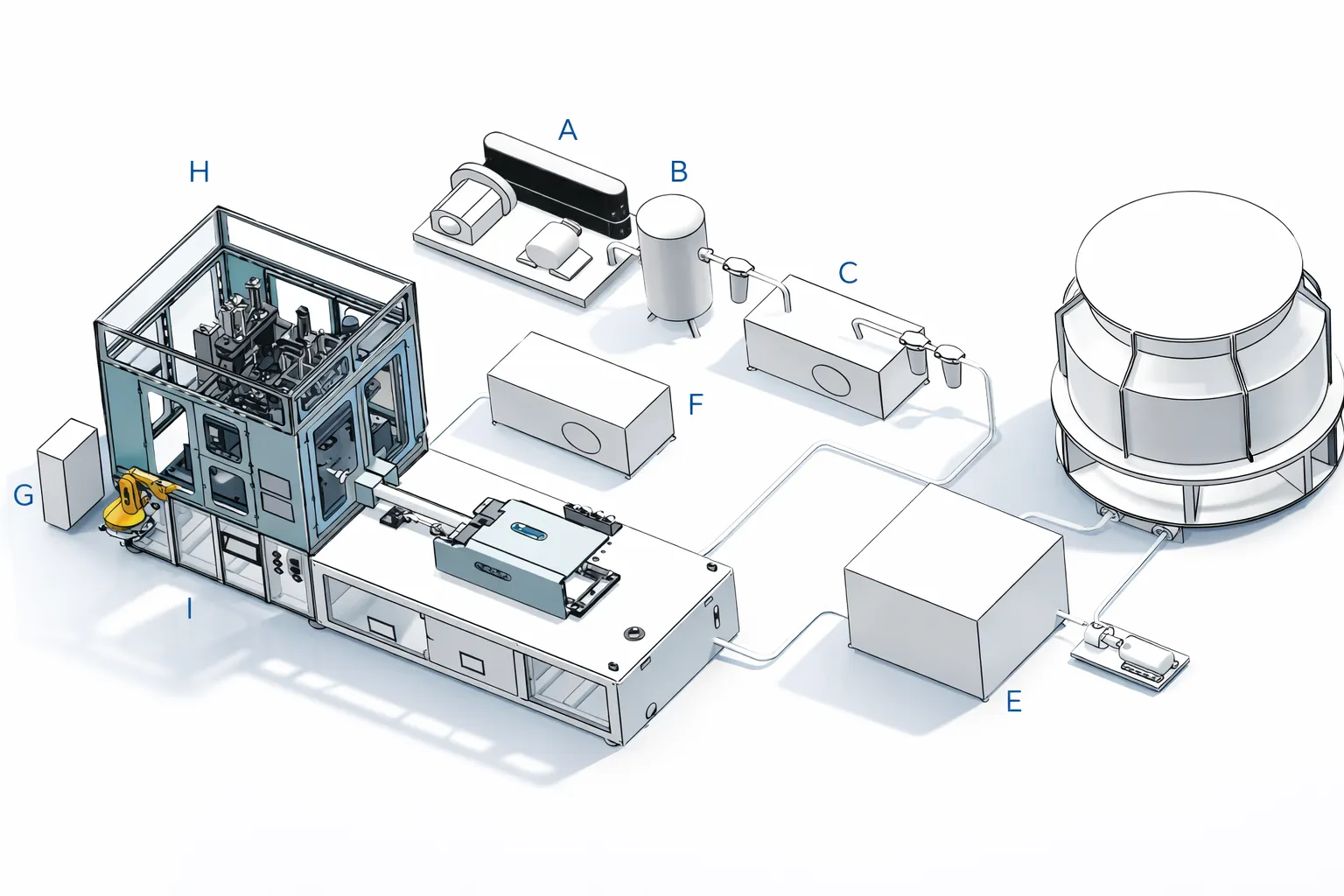
The screw and barrel assembly is the most expensive wear component in the ISBM machine and the one most sensitive to operating practice. Two specific practices determine the service life of the screw and barrel more than any other factor:
Purging Procedure Between Resin Changes
When changing from one resin to another — particularly when transitioning between PET and PETG, or between standard PET and Tritan — the barrel must be purged of the previous resin before the new resin is introduced. A residual PET charge in the barrel at 260 °C (Tritan processing temperature) will degrade at a higher rate than PET’s normal processing temperature of 270–285 °C — and the degraded PET will contaminate the first batches of Tritan production with brown streaks or black specks.
Standard purging procedure for ISBM machines:
- Reduce barrel temperature to the lower of the two resins’ processing temperatures.
- Inject the screw forward to minimum cushion 5 times to expel the current resin through the nozzle.
- Load the new resin into the hopper and recover the screw 3 times, purging the mixed melt each time.
- Increase barrel temperature to the new resin’s target and allow 15 minutes for stabilisation.
- Purge 3 more times; inspect purge material colour and clarity against the new resin’s standard before accepting production.
Screw Wear Indicators — When to Replace Before Barrel Damage
Screw wear manifests as progressive shot weight inconsistency — the cushion position varies more than usual, shot weight variation increases beyond ±0.3 g, and back-pressure cannot be maintained consistently. These are the operational symptoms of a screw whose flight tips have worn below the critical clearance threshold. The measurement-based criterion for screw replacement:
Screw Replacement Decision Criteria
New screw clearance: 0.05–0.08 mm (radial, screw flight OD to barrel bore ID)
Warning threshold: 0.12–0.15 mm — plan screw replacement within next 200 hours; monitor shot weight CV weekly
Mandatory replacement: > 0.15 mm — replace screw before further production. Above this clearance, melt can bypass the screw flights, reducing plasticisation efficiency and increasing shot weight variation. If the screw is operated above 0.20 mm clearance, the bypass melt begins to erode the barrel bore — at which point both screw and barrel must be replaced, at 3–5× the cost of a screw-only replacement.
Maintenance Log Template
A written maintenance log — whether paper-based or digital — is the minimum documentation required to manage a preventive maintenance programme effectively. Without a log, maintenance is reactive by default: tasks are completed when problems appear, not at the correct intervals. With a log, the maintenance team can see at a glance which intervals are approaching, what was found at the last check, and whether a measurement (oil level, screw clearance, thermocouple calibration offset) is trending toward a threshold. Regulators and OEM warranty claims also require maintenance records as evidence of proper machine care. If a Korea troubleshooting is needed, our team will first ask to see the maintenance log when assessing a machine problem remotely.
● Maintenance Log — Minimum Required Fields
■ Machine serial number and model
■ Date and shift; operator name
■ Running hours at time of check (from machine HMI hour counter)
■ Maintenance interval performed (daily / weekly / monthly / 500 hr / 2,000 hr)
■ Each task: completed ✓ / deferred (reason) / defect found (description)
■ Measurements recorded (oil level, thermocouple offset, screw clearance where measured)
■ Parts replaced (part number, quantity, supplier lot number)
■ Corrective action taken if defect found; follow-up action required
■ Supervisor sign-off
◆ Ключов извод
A complete ISBM machine maintenance programme — daily shift-start checks, weekly, monthly, 500-hour, 2,000-hour, and annual overhaul tasks — is the single investment with the highest return in any ISBM production operation. The cost of the programme (labour time and consumable parts) is typically 2–4% of the machine’s capital cost per year. The cost of the unplanned stoppages, quality failures, and accelerated wear that a neglected machine produces is typically 8–15% of machine capital cost per year. The maintenance programme pays for itself three to five times over in the first year of consistent application.
Заключение
Achieving 95% uptime on an ISBM machine is a maintenance discipline, not a machine specification. The programme in this guide — structured by interval from daily checks to annual overhaul — provides the framework; the maintenance log provides the accountability; and the operator’s habit of completing the daily first-article inspection provides the earliest warning system for developing problems. None of these requires specialist equipment or unusual skills. They require consistency and a management culture that treats planned maintenance time as a production investment, not as a production interruption.
Korea Ever-Power provides machine-specific preventive maintenance schedules with each HGY and HGS series machine delivery — tailored to the specific machine model, drive system, and production programme — as part of the commissioning documentation package. Contact Korea Ever-Power’s technical support team for machine-specific maintenance scheduling or for guidance on a maintenance programme for an existing installation.
Относно тази статия: Prepared by the Korea Ever-Power Technical Team based on field service experience across HGY and HGS series ISBM machine installations. Maintenance intervals and measurement thresholds are based on Korea Ever-Power’s service records and recommended practice; specific machines may have different intervals per the machine-specific maintenance manual supplied at delivery. All maintenance work should be performed by qualified personnel with the machine in a safe locked-out state per the machine’s safety procedures.
Свързано четиво: ISBM Machine Troubleshooting — 12 Defects, Causes, and Fixes | How to Choose an ISBM Machine — 8 Specifications | ISBM Machine Price — Total Cost of Ownership
Редактор: Cxm