ISBM Preform Design Engineering:
Gewicht, L/D-verhouding en poortgeometrie — De basis die Koreaanse flessenproducenten nodig hebben voordat ze een mal bestellen.
Elke kwaliteitsfout in ISBM-flessen — wandverdunning, spanningsverbleking, aanspuitresten, onvoldoende CO₂-barrièrewerking — kan worden herleid tot een van de drie ontwerpbeslissingen voor de voorvorm die maanden vóór de eerste productierun worden genomen. Deze handleiding biedt de technische berekeningen die Koreaanse ISBM-producenten nodig hebben om die beslissingen in één keer goed te nemen.
BBR 8–15 voor PET
Poortrestant ≤0,5 mm
1. Waarom het ontwerp van de voorvorm de meest cruciale beslissing is bij ISBM
Koreaanse ISBM-producenten investeren standaard 15-45 miljoen KRW in blaasvormmatrijzen en honderden miljoenen meer in machineplatformen, maar besteden minder dan drie werkdagen aan de specificatie van de voorvorm. Deze onevenwichtigheid is in de praktijk steevast kostbaar. Het ontwerp van de voorvorm bepaalt drie zaken die na de matrijsbouw door geen enkele aanpassing van de machineparameters kunnen worden overruled: de totale hoeveelheid materiaal in de fles, waar dat materiaal terechtkomt na het blazen, en of de spuitzone een cosmetisch acceptabele flesbodem oplevert bij productiesnelheid.
De twee productiefouten die in Koreaanse ISBM-productieprocessen het vaakst ten onrechte worden toegeschreven aan onjuiste machine-instellingen of matrijstemperatuur zijn: ongelijke wanddikte en spanningsverbleking — beide ontstaan door L/D-verhoudingen buiten het optimale bereik of door onjuist berekende specificaties voor de poortzone. Het diagnosticeren van deze defecten op machineniveau is altijd trager en duurder dan ze te voorkomen in de ontwerpfase van de voorvorm.
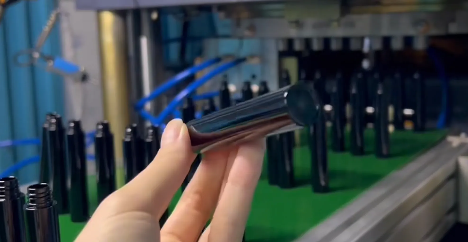
Een preform is niet zomaar een "standaardonderdeel" uit een catalogus. Het is een nauwkeurig ontworpen component waarvan de geometrie de structurele eigenschappen van de uiteindelijke fles bepaalt. Een fout van 0,1 mm in de wanddikte van de spuitopening vertaalt zich in een meetbare verandering in de hoogte van de spuitopening, de kristalliniteit van de flesbodem en de barstdruk. Een fout van 0,5 mm in de lengte van de preform verandert de haalbare axiale rekverhouding met 3–6% – genoeg om de barstdruk buiten het optimale bereik te brengen. Het correct afstellen van de preformgeometrie vóórdat de matrijs wordt bewerkt, is de meest effectieve kwaliteitsverbetering die Koreaanse ISBM-producenten tot hun beschikking hebben.

2. Berekening van het voorvormgewicht: de technische standaard van ±0,3 g
Het gewicht van de preform wordt berekend op basis van vier additieve componenten, die elk expliciet moeten worden berekend in plaats van geschat: (1) netto fleswandmateriaal – de totale polymeermassa die aanwezig is in de afgewerkte fles; (2) materiaaltoeslag voor de poortzone – doorgaans 8–121 TP3T van het netto flesgewicht voor puntpoortontwerpen, rekening houdend met het poortrestant en de massa van de poortovergangszone; (3) materiaal van de halssteunrand – de massa van de halszone die deel blijft uitmaken van de afgewerkte fles en niet wordt uitgerekt; en (4) aandeel van de verliezen in het hotrunner-systeem per caviteit, indien van toepassing.
De tolerantiespecificatie van ±0,3 g bestaat om economische redenen die op grote schaal van belang zijn. Bij een voorvorm van 20 g voor een waterfles van 500 ml, tegen de huidige Koreaanse PET-prijs van KRW 1.800/kg, bedraagt het kostenverschil tussen een voorvorm van 19,7 g en een van 20,3 g KRW 1,08 per fles. Bij een jaarlijkse productie van 10 miljoen eenheden vertegenwoordigt deze variabele tolerantie een jaarlijkse variatie in materiaalkosten van KRW 10,8 miljoen – een bedrag dat in de meeste Koreaanse ISBM-winst- en verliesrekeningen ontbreekt, omdat de tolerantie voor het gewicht van de voorvorm niet schriftelijk is vastgelegd en daarom niet consistent wordt gemeten. Het cijfer van ±0,3 g is geen willekeurige voorzichtigheid; het is de drempel waarboven de variatie in materiaalkosten commercieel significant wordt bij Koreaanse productievolumes.
Koreaanse producenten moeten het gewicht van de voorvorm tot twee decimalen nauwkeurig specificeren — “21,45 g ±0,3 g” — in elke matrijsbestelling, en niet “ongeveer 21 g”. Matrijsleveranciers die het gewicht van de voorvorm zonder tolerantie opgeven, hebben geen mechanisme om de spuitgietprestaties van hun eigen matrijs te controleren aan de hand van de specificaties en kunnen niet aansprakelijk worden gesteld wanneer het productiegewicht afwijkt. Het vereisen van een tolerantie in de bestelling is geen pedanterie; het is de contractuele basis voor acceptatietesten.
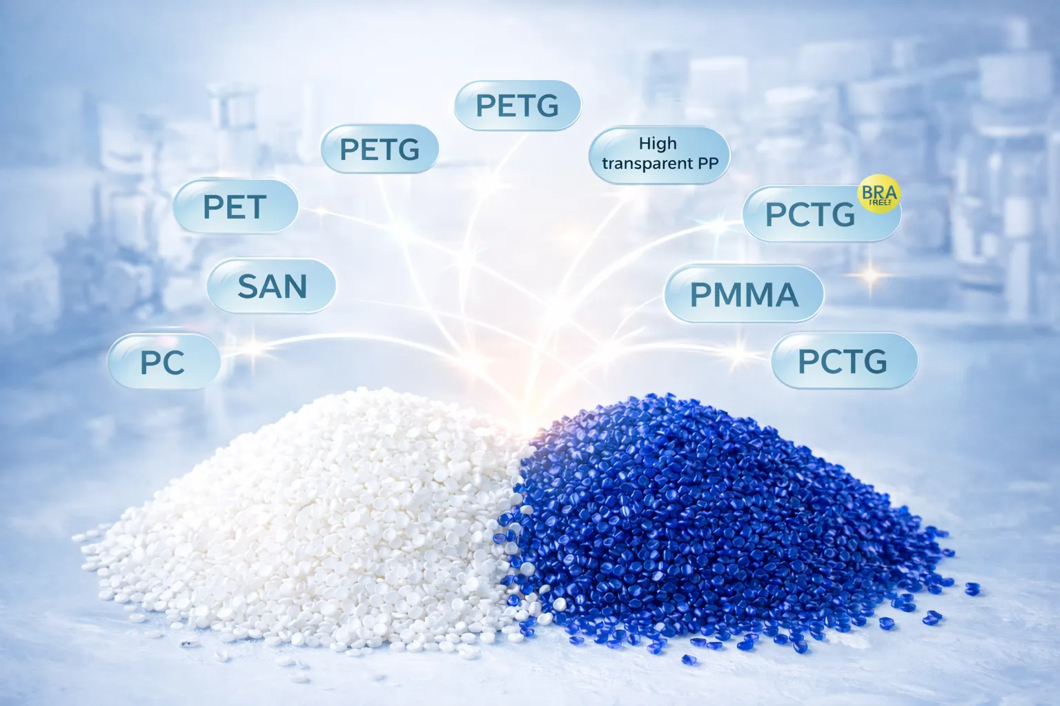
Een factor die vaak over het hoofd wordt gezien bij de gewichtsberekening van preforms is het effect van het rPET-gehalte. Wanneer De tolerantie voor het gewicht van rPET-preforms wordt aanzienlijk kleiner. In vergelijking met nieuw PET – omdat de variatie in intrinsieke viscositeit van gerecycled PET (rPET) leidt tot variaties in viscositeit van injectie tot injectie, die het injectieproces bij standaarddrukinstellingen niet volledig kan compenseren – ervaren Koreaanse producenten die hun gewichtstolerantiespecificatie voor rPET-mengsels niet aanpassen consequent hogere afvalpercentages dan hun referentiewaarden voor nieuw PET zouden voorspellen.
3. Relatie tussen de L/D-verhouding en de axiale rekverhouding
De L/D-verhouding van de voorvorm — de lengte van het lichaam gedeeld door de buitendiameter — is de belangrijkste ontwerpvariabele die de haalbare axiale rekverhouding (As) bepaalt. Een langere, smallere voorvorm met hetzelfde gewicht bereikt een hogere axiale rek in dezelfde holte dan een kortere, bredere voorvorm. Dit is belangrijk omdat As een van de twee componenten is van de biaxiale opblaasverhouding (BBR) die de oriëntatieafhankelijke eigenschappen van de uiteindelijke flessenwand bepaalt: treksterkte, gasbarrière, optische helderheid en prestaties bij belasting van bovenaf nemen allemaal toe met de BBR tot aan het oriëntatieplafond van het materiaal.
As (axiale rekverhouding) = H_fleslichaam ÷ H_voorvormlichaam
Rs (radiale rekverhouding) = D_fleslichaam ÷ D_voorvormlichaam
BBR (biaxiale opblaasverhouding) = As × Rs/* Optimale bereiken van de Koreaanse ISBM */
PET maagdelijk: BBR 8–15 (piek = ~11)
PETG: BBR 6–12 (piek = ~9)
PP: BBR 4–8 (smal procesvenster)/* Uitgewerkt voorbeeld — fles plat water van 500 ml */
As = 140 mm ÷ 38 mm = 3,68×
Rs = 65 mm ÷ 22 mm = 2,95×
BBR = 3,68 × 2,95 = 10.86 ✓ binnen PET-optimum
Wanneer de BBR onder de 8 komt, ontwikkelt de flessenwand onvoldoende biaxiale oriëntatie. De moleculaire ketens blijven grotendeels amorf, wat resulteert in een lagere optische helderheid van PET, een inferieure CO₂-barrière in koolzuurhoudende flessen, een lagere treksterkte per eenheid wanddikte en een verminderde draagkracht ten opzichte van de materiaalkosten van de fles. Wanneer de BBR boven de 15 komt, ondervindt de poortzone een te hoge rekspanning tijdens de initiële rekfase. Omdat PET een materiaal is met rekverharding – de weerstand tegen rek neemt sterk toe naarmate de oriëntatie toeneemt – bereikt de poortzone, die de hoogste lokale rek ondergaat, rekverhardingsfalen voordat de rest van de fles de gewenste oriëntatie bereikt. Het gevolg is scheuren in de poortzone en een verhoogd afvalpercentage.
Voor Koreaanse ISBM-formaten variëren de geschikte L/D-verhoudingen van 1,8 voor cosmetische potjes met een brede opening tot 4,2 voor hoge flessen met orale vloeistoffen voor farmaceutische producten. Koreaanse producenten die nieuwe SKU's ontwikkelen zonder de gewenste BBR te berekenen op basis van de flesgeometrie, doen in feite maar wat. De kosten voor herwerking wanneer die schatting een BBR oplevert die buiten het optimum valt, zijn doorgaans 15 tot 25 keer hoger dan de kosten van de berekening.
4. Ontwerp van de wanddiktezone: het voorspellen van de fles op basis van de voorvorm.
Het wanddikteprofiel van een voorvorm is opzettelijk niet-uniform — het moet zo ontworpen zijn dat het de niet-uniforme rek compenseert die optreedt op verschillende axiale posities tijdens het blazen. Drie zones vereisen een expliciete specificatie van de dikte:
Poortovergangszone (2,0–2,5× lichaamswand): De zone met de hoogste spanning in het blaasproces. Er moet materiaal aan de flesbodem worden toegevoerd met lagere lokale rekverhoudingen dan in de rompzone. Een onvoldoende wanddikte van de poortzone leidt tot een dunnere bodem; een te dikke wanddikte van de poortzone is de grootste oorzaak van te zware Koreaanse ISBM-flessen. Een poortzonewanddikte van 4,2 mm op een voorvorm van 20 g, terwijl 3,6 mm voldoende zou zijn, voegt 0,4–0,6 g per voorvorm toe – wat overeenkomt met 5–7 miljoen KRW per jaar aan verspild materiaal bij een productie van 10 miljoen flessen.
Lichaamszone (muur met minimale specificaties): Deze zone heeft de dunste wand omdat deze de grootste lokale axiale en radiale rek ondergaat. De minimaal acceptabele wanddikte van de afgewerkte fles (doorgaans 0,18–0,28 mm, afhankelijk van de toepassing) wordt via de lokale BBR (Ballistic Body Reduction) omgerekend naar de vereiste wanddikte van de voorvorm. Deze omgekeerde berekening – van de minimale wanddikte van de afgewerkte fles naar de vereiste wanddikte van de voorvorm – is de fundamentele berekening voor het ontwerp van de voorvorm die de meeste Koreaanse matrijzenleveranciers niet expliciet uitvoeren.
Schouderovergangszone (1,4–1,8× lichaamswand): De geometrische beperking bij de overgang van schouder naar hals beperkt de radiale rek, waardoor een zone met verminderde oriëntatie en verhoogde wanddikte ontstaat ten opzichte van de rest van het lichaam. De overgangswand van de schouder moet zodanig worden gespecificeerd dat overmatige materiaalophoping wordt voorkomen. "Schouderknobbels", zichtbaar als waasbanden in transparante K-Beauty-flessen, zijn een klassiek symptoom van overdimensionering van de schouderzone in de voorvorm.
5. Poortgeometrie: Puntpoort versus kleppoort
De poortgeometrie bepaalt de hoogte van de poortrestanten, het overgangsprofiel van de poortzonewand en de interactie met het hotrunner-systeem. In de Koreaanse ISBM-productie worden drie typen gebruikt, elk geschikt voor specifieke toepassingen:
Puntpoort (standaard)
Diameter: 0,8–1,5 mm · Landlengte: 0,8–1,2 mm
Overblijfsel: Hoogte van 0,2–0,5 mm na poortonderbreking. Kan niet worden verwijderd.
Koreaans gebruik: PET voor dranken, voedingsmiddelen, persoonlijke verzorging en huishoudelijke producten. Geschikt voor alle toepassingen waarbij een basisrest van 0,5 mm acceptabel is.
Klepafsluiter (Premium)
Servopen sluit poort na vulling · Bijna geen restanten
Overblijfsel: <0,1 mm markering. Vrijwel onzichtbaar bij winkelverlichting.
Koreaans gebruik: Premium K-Beauty PETG (Sulwhasoo, The Whoo), farmaceutische KFDA-goedgekeurde orale vloeistof. Vereist wanneer de basisrest niet meer dan 0,2 mm mag bedragen.
Zijpoort (Specialiteit)
Excentrische poortpositie · Voegt complexiteit toe aan de looproute
Overblijfsel: Niet op de basis zichtbaar als de fles ondoorzichtig is; bij sommige ontwerpen verborgen door de vorm van de basis.
Koreaans gebruik: Containers met een brede opening (63 mm of meer) waarbij het centrale poortdeel op een goed zichtbare plaats terechtkomt.
Voor toepassingen met afsluiters en schuifafsluiters, timing van de poortzone voor hot runners De timing moet nauwkeurig gesynchroniseerd zijn met de sluiting van de klepstift — de stift moet sluiten terwijl het materiaal in de poortzone nog vloeibaar genoeg is om een goede afdichting te garanderen, maar voordat de voorvorm uit de injectieholte loskomt. Een timingfout van 30 ms in beide richtingen resulteert in een uitstekende afdruk (te vroeg) of vertraging in de poortzone (te laat). Koreaanse Ever-Power EV-machines ondersteunen kleptiming met een resolutie van 5 ms als standaardfunctie.
6. Ontwerp en afdichtingsprestaties van de halsafwerking
De halsafwerkingszone wordt door middel van spuitgieten tot de uiteindelijke afmeting gevormd – deze rekt niet uit tijdens het blaasproces. Elke schroefdraadvorm, hoogte van de steunrand, afmeting van de transferrand en vlakheid van het afdichtingsoppervlak wordt permanent ingesteld bij het spuitgietstation. Dit betekent dat de dimensionale nauwkeurigheid van de halsafwerking volledig wordt bepaald door de geometrie van de spuitgietmatrijs en de koeling – en niet door parameters van het blaasproces.
Koreaanse ISBM-producenten die een variatie in het aanhaalmoment van de sluiting ervaren van meer dan ±15% ten opzichte van de streefwaarde, moeten eerst de plaatsing van de koelkanalen in de halszone en de temperatuur van de koelvloeistof controleren voordat ze aannemen dat het probleem in de specificatie van de sluiting of de vullijnapparatuur ligt. Het mechanisme: onvoldoende koeling in de afwerkingszone van de hals zorgt ervoor dat de schroefdraadvorm onder de uitwerpkracht enigszins vervormt. De schroefdraadgeometrie is correct bij kamertemperatuur wanneer deze koud wordt gemeten, maar bij productietemperaturen – wanneer de machine continu draait en de halsring nooit volledig afkoelt tussen de cycli – zorgt de cumulatieve thermische vervorming ervoor dat de buitendiameter van de schroefdraad met 0,08–0,15 mm verschuift. Dit is voldoende om een inconsistente pompdruk of aanhaalmoment van de sluiting te veroorzaken bij een vullijn van een Koreaans merk dat 120 flessen per minuut verwerkt.
Specificatie voor de koeling van de halszone: speciale koelkanalen houden de temperatuur van het staal in de halszone op 15–25 °C, onafhankelijk van het circuit in de voorvormzone dat op 8–15 °C werkt voor optimalisatie van de cyclustijd. Deze onafhankelijkheid is belangrijk: overkoeling van de voorvormzone om de cyclustijd te verkorten mag niet worden bereikt door de koelvloeistofstroom van de halszone af te leiden.
7. Vijf Koreaanse flesformaten — Referentietabel voor voorvormparameters
De volgende tabel geeft geverifieerde startparameters voor de vijf meest voorkomende ISBM-flesformaten in Korea. Deze waarden vertegenwoordigen de technische aanbevelingen van Ever-Power in Korea, gebaseerd op productiegegevens van Koreaanse klantlijnen. Het zijn geen theoretische berekeningen, maar gevalideerde startwaarden die consequent een optimale BBR (Bulk Barrel Rate) opleveren bij de eerste proef.
| Flesformaat | Hars | Gewicht van het voorvormstuk | L/D-ratio | Doelwit als | Doelprijs Rs | BBR |
|---|---|---|---|---|---|---|
| 100 ml K-Beauty PETG-serum | PETG | 9,5–11 g | 2.4 | 3,2× | 2,6× | 8.3 |
| 500 ml plat water (PCO 1881) | PET maagd | 17–21 g | 3.2 | 3,7× | 2,9× | 10.7 |
| 1L eetbare olie PET (38mm BPF) | PET maagd | 34–40 g | 3.5 | 4.0× | 2,7× | 10.8 |
| 50 ml farmaceutische orale vloeistof PET | PET maagd | 5,5–7 g | 2.1 | 3,5× | 2,5× | 8.8 |
| 12L waterkan (halsdiameter 63 mm) | PET maagd | 310–360 g | 1.9 | 3,3× | 3,5× | 11.6 |
Tabel 1. Referentieparameters voor Koreaanse ISBM-voorvormen — gevalideerde uitgangspunten op basis van productiegegevens van Ever-Power in Korea. De uiteindelijke parameters moeten worden bevestigd door middel van een 8-punts wanddiktemeting op 30 productiemonsters. Het gewicht van de halsafwerking is inbegrepen in de gewichtsgegevens van de voorvorm.
8. rPET-voorvormontwerp: IV-variantie en nauwere toleranties
De Koreaanse K-EPR-regelgeving schrijft vanaf januari 2026 een gehalte van 101 TP3T voor gerecycled PET (rPET) voor, oplopend tot 301 TP3T in 2027 en 501 TP3T in 2030. Bij elke stap in de naleving neemt de impact van de variatie in de intrinsieke viscositeit (IV) van rPET op de gewichtsconsistentie van de preform toe. Nieuw PET wordt doorgaans geleverd met een IV-variatie van ±0,02 dl/g binnen een batch. Gerecycled rPET vertoont een variatie van ±0,06–0,12 dl/g, zelfs binnen één enkele SSP-behandelde batch. Deze IV-variatie veroorzaakt variaties in de smeltviscositeit van injectie tot injectie, die het injectieproces bij standaard drukinstellingen niet volledig kan compenseren.
Voor rPET-mengsels boven 20% zijn twee aanpassingen aan het ontwerp van de voorvorm verplicht: de injectiedrukregeling moet worden aangescherpt van ±3 bar (acceptabel voor nieuw PET) naar ±1,5 bar, en de wanddikte van de poortzone moet met 10% worden verhoogd ten opzichte van de specificatie voor nieuw PET om rekening te houden met de lagere vloeibaarheid van rPET met een hogere IV-waarde aan het einde van de IV-verdeling van de batch. Koreaanse producenten die rPET in een bestaand ontwerp van nieuwe PET-voorvormen gebruiken zonder deze aanpassingen, zien consequent een toename van het aantal defecten in de poortzone bij de eerste rPET-proef (15–35%) – een volledig voorspelbaar en volledig te voorkomen probleem.
De juiste aanpak is om aparte specificaties voor de voorvorm te ontwerpen voor elk rPET-gehalte (10%, 30%, 50%) in plaats van de specificatie voor zuiver PET stapsgewijs aan te passen bij elke conformiteitsstap. De gatezone-wand en het injectiedrukvenster zijn niet hetzelfde bij 10% en 30% rPET, en het behandelen ervan alsof ze hetzelfde zijn, vormt een kwaliteitsrisico dat toeneemt met elke K-EPR-stapwijziging.
9. De zevenstappenworkflow voor preformvalidatie
De validatieworkflow zet een technische specificatie van een voorvorm om in een productieklaar ontwerp, met gedocumenteerd bewijs bij elke stap. Koreaanse producenten die stappen in deze workflow overslaan om de projectduur te verkorten, besteden steevast meer kalendertijd en KRW aan herstelwerkzaamheden dan de overgeslagen stappen zouden hebben gekost.
Stap 1
Definieer de volledige flesspecificatie
Doelgewicht (±0,5 g), alle afmetingen met toleranties, minimale bovenbelasting (N), barrière-eisen en standaard voor halsafwerking. Dit is het ankerdocument — alle daaropvolgende beslissingen over de voorvorm verwijzen naar deze specificatie.
Stap 2
Bereken de doel-BBR en voer de geometrie uit.
Bereken As, Rs en BBR op basis van de afmetingen van de fles en de voorvorm. Controleer of de BBR binnen 8–15 ligt voor PET en binnen 6–12 voor PETG. Pas de L/D-verhouding aan als de BBR buiten dit bereik ligt.
Stap 3
Ontwerp het wanddikteprofiel per zone.
Poortzone (2,0–2,5× lichaamsdikte), lichaamszone (minimum per BBR), schouderzone (1,4–1,8× lichaamsdikte), nekzone (geen rek). Documenteer alle wanddiktes met een tolerantie van ±0,05 mm voor elke zone.
Stap 4
Specificeer de poortgeometrie en de parameters van het hete kanaal.
Selectie van poorttype (punt-/klep-/zijpoort), poortdiameter, lengte van de aanloopbaan, specificatie van de restanten. Voor kleppoorten: bevestig het sluitingsvenster en de geometrie van de spuitmond met de leverancier van de hotrunner voordat de matrijsbewerking begint.
Stap 5
Eerste proef met injectie van het artikel — minimaal 50 voorvormen
Weeg alle 50 voorvormen op een balans met een resolutie van 0,01 g. Noteer het gemiddelde en de standaardafwijking — deze moet binnen ±0,3 g vallen. Snijd 5 voorvormen doormidden en meet de wanddikte in alle zones ten opzichte van de specificaties.
Stap 6
Blaasvalidatie — 100 flessen, 8-punts wandmapping
Breng de wanddikte in kaart op 8 gestandaardiseerde posities op 30 flessen. Bereken het gemiddelde en de variatiecoëfficiënt (CV%) op elke positie. Controleer of er geen zone onder het minimum ligt. Verifieer of de werkelijke BBR overeenkomt met de ontwerpberekening.
Stap 7
Prestatietesten en goedkeuring voor productie
Bovenbelastingstest (N), valtest (1,5 m, 5 oriëntaties), CO₂- of O₂-barrièremeting indien nodig. Stabiliteitstest met 2000 schoten. Definitief kwaliteitsrapportagepakket afgegeven. Ontwerp van de voorvorm vrijgegeven voor inbedrijfstelling van de productiegereedschappen.
10. Koreaanse Ever-Power Preform Engineering Service
Het Koreaanse Ever-Power biedt de ontwikkeling van specificaties voor voorvormen aan als een gestructureerde engineeringdienst – geen gratis adviesgesprek, maar een gedocumenteerd eindproduct dat door het engineeringteam wordt geproduceerd voordat er ook maar één matrijs wordt gefreesd. Het pakket omvat BBR-berekening met verificatie, zone-per-zone specificatie van de wanddikte, aanbeveling voor poortgeometrie met specificatie van restmateriaal, rPET-aanpassingsparameters voor het opgegeven K-EPR-gehalte en een meetplan voor het eerste artikel waarin precies wordt gespecificeerd wat er moet worden geverifieerd en met welke tolerantie voordat de voorvorm wordt goedgekeurd voor de blaasproef.
Koreaanse producenten die deze service inschakelen vóór de matrijsbestelling, reduceren het aantal ontwikkelingsiteraties bij de eerste poging steevast van het gemiddelde van 2,8 proefnemingen in de Koreaanse ISBM-industrie naar 1,2 proefnemingen. De besparing zit niet in de kosten voor de engineeringservice, maar in de 1,5 tot 4 miljoen KRW aan herwerkkosten per vermeden proefneming, de 3 tot 8 weken ontwikkeltijd die per project worden bespaard en het wegnemen van de kwaliteitsonzekerheid die ontstaat wanneer men overgaat tot productie met een voorvorm waarvan de wanddikteverdeling nooit expliciet is berekend.
Veelgestelde vragen
Preform Engineering Service
Een nieuwe ISBM-flesvariant ontwikkelen?
Zorg voor een correcte specificatie van het voorvormstuk voordat de matrijs wordt bewerkt.
Het Koreaanse Ever-Power levert een schriftelijk engineeringpakket voor de voorvorm – inclusief BBR-berekening, zonewanddikte, poortgeometrie en rPET-aanpassingsparameters – vóórdat er in de matrijs wordt geïnvesteerd. Geen giswerk en herwerkingen meer.
Gerelateerde bronnen
Gereedschap op maat
Koreaans EverPower Custom ISBM-matrijzenprogramma
Elke bestelling voor een matrijs op maat omvat een technische beoordeling van het voorvormstuk — gewicht, BBR, poortgeometrie — voordat de matrijsbewerking begint.
Procesoptimalisatie
Optimalisatie van de ISBM-cyclustijd — Koreaans raamwerk met 5 hefbomen
De juiste wanddikte van de voorvorm verkort de conditioneringstijd met 0,3–0,8 seconden per cyclus – één van de vijf mogelijkheden om de cyclustijd te verkorten die Koreaanse producenten kunnen benutten.
Vormselectie
ISBM Matrijsselectie — Koreaans koperskader met 9 factoren
De compatibiliteit van het voorvormontwerp is factor 2 van de 9 in het uitgebreide Koreaanse ISBM-mallenselectiekader.


