
PROCESS GUIDE · 3-STATION IBM · CORE ROD MECHANISM · KOREA EVER-POWER ZQ SERIES
How IBM Works:
3-Station Injection Blow Molding Process
Injection blow molding produces a finished hollow container in a single machine through three sequential stations — injection, blow, strip — all on a single rotating turret carrying core rods between stations. Understanding the 3-station mechanism explains why IBM achieves ±0.05 mm neck precision, zero base flash, uniform wall thickness and no parting line on the container body — capabilities that emerge directly from the process architecture rather than from secondary operations.
Core Rod Mechanism
Zero Flash · No Parting Line
KOREA EVER-POWER · ANSAN-SI, GYEONGGI-DO · JULY 2026
PROCESS REFERENCE · IBM 3-STATION ARCHITECTURE PARAMETERS
STATIONS
3
Injection → Blow → Strip on single rotating turret
TURRET ROTATION
120°
Per step · 0.3–0.5 s · simultaneous 3-station operation
NECK PRECISION
±0.05 mm
OD across all cavities — injection-moulded, blow-phase-isolated
TYPICAL CYCLE TIME
3.5–6.5 s
Format and material dependent — 10 ml pharma to 500 ml shampoo
SECTION 01
IBM 3-Station Architecture Overview
IBM 3-STATION PROCESS FLOW · ALL THREE STATIONS OPERATE SIMULTANEOUSLY EACH CYCLE
INJECTION
Preform Formation
Core rod enters injection mould cavity. Molten HDPE injected around core rod under 100–150 MPa. Neck thread and features formed at ±0.05 mm in the injection mould’s neck insert.
Preform tube solidifies on core rod in 0.4–1.0 s hold + cooling. Core rod surface defines preform interior bore. Preform body ready for blow inflation.
BLOW
Container Formation
Core rod + preform enters blow mould cavity. Blow air (0.5–0.95 MPa) exits through core rod tip. Preform body inflates against blow mould cavity wall in 0.8–1.5 s.
Container body adopts blow mould shape exactly. Neck on core rod unchanged — blow pressure only acts below the neck zone. Container body cools 0.9–2.0 s dwell.
STRIP
Container Ejection
Core rod + finished container enters stripping station. Stripping tool engages container shoulder. Core rod retracts; container slides off onto output conveyor.
Clean core rod ready for next injection cycle. One complete container produced per core rod per cycle. All three stations operate simultaneously — 3× throughput vs sequential process.
Each cycle: all three stations active simultaneously. A 20-cavity ZQ80 produces 20 finished containers per cycle. At 4-second cycle time: 5 cycles/minute × 20 containers = 100 containers/minute = 6,000/hour.
IBM’s 3-station architecture is what distinguishes it from all other blow molding processes. The three stations are not sequential steps carried out one at a time — they operate simultaneously in every cycle. While Station 1 is injecting a new preform, Station 2 is blowing the previous preform into a container, and Station 3 is stripping the container produced in the preceding cycle. This parallel operation is what makes IBM’s production rate comparable to EBM despite the additional process steps — IBM spends one cycle time performing all three operations, not three cycle times performing them sequentially. The full context of IBM’s advantages over other blow molding processes is covered in the injection blow molding overview guide.
The rotating turret carries one set of core rods for each station simultaneously. A 20-cavity ZQ80 has 20 core rods in total — 20 are in the injection station, 20 in the blow station and 20 in the stripping station at the same moment. The turret carries all 60 core rods (3 sets × 20) at once, rotating 120° between stations in 0.3–0.5 seconds. This architecture means that every core rod produces exactly one finished container per machine cycle, and the machine output per cycle equals the cavity count — a direct, simple relationship that makes IBM production planning straightforward.
SECTION 02
Station 1 — Preform Injection Moulding
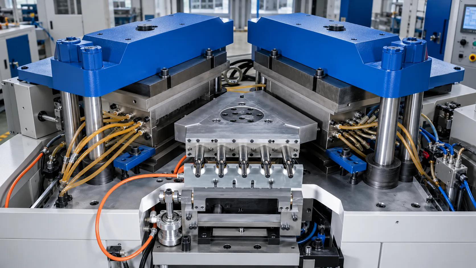
Station 1 is where the container’s neck geometry is permanently defined. The injection mould’s neck insert — a precision-machined S136 stainless steel insert at the top of each cavity — forms the thread, engagement features (CRC bead, pump retention bead, dispensing nozzle) and sealing land exactly as machined, at ±0.05 mm tolerance across all cavities simultaneously in a single injection shot.
MOULD CLOSE + CORE ROD ENTRY · 0.2–0.4 s
The injection mould closes around the core rods as the turret indexes to Station 1. The injection mould’s two halves (A-side and B-side) clamp shut with the full ZQ machine clamping force applied — 400 KN on ZQ40 to 1,350 KN on ZQ135. The core rod is now centred within the closed injection mould cavity, with the annular space between the cavity wall and the core rod surface defining the preform tube geometry, and the neck insert at the top of the cavity surrounding the core rod’s neck zone to form the thread and other features.
INJECTION FILL · 0.8–2.0 s
The plasticising screw advances, injecting the metered HDPE shot through the hot runner manifold into all cavities simultaneously. The hot runner maintains the HDPE at melt temperature (195–225°C) through the manifold to the gate at the base of each core rod’s tip — ensuring all cavities fill at the same time and temperature regardless of their position in the mould. Injection pressure: 90–150 MPa, with fill time 0.8–2.0 s depending on preform size and HDPE viscosity (MI).
HOLD + COOLING · 0.4–1.0 s + 0.5–1.5 s
After fill, the screw holds pressure (50–75% of peak injection pressure) to compensate for HDPE volumetric shrinkage as the preform solidifies. Cooling water circuits in the injection mould (set at 12–20°C for pharmaceutical, 18–28°C for household/personal care) rapidly solidify the preform from the cavity wall inward. The preform solidifies on the core rod — the core rod surface defines the preform’s inner bore diameter and surface finish. Cooling must solidify the preform sufficiently to maintain dimensional stability when the mould opens, but not so completely that the preform loses the residual heat needed for blow inflation at Station 2.
MOULD OPEN + TURRET ROTATION · 0.3–0.5 s
The injection mould opens while the preform remains on the core rod — held by the shrink grip of the HDPE onto the core rod surface. The turret rotates 120° to carry the preforms to Station 2. At the same time, a new set of empty core rods enters Station 1 for the next injection cycle. The preform must retain sufficient heat (typically 90–130°C at the body wall surface when it enters the blow mould) to allow inflation without cracking — too cold and the preform body resists blowing; too hot and the neck zone that was precisely injection-moulded at Station 1 can distort during turret transit.
SECTION 03
Station 2 — Blow Moulding
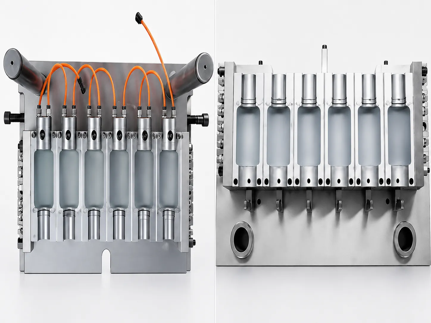
Station 2 is where the preform tube becomes a finished container body. The blow mould is the only component that determines container body shape — IBM’s body geometry flexibility (any cross-section, any volume, any surface texture) comes entirely from the blow mould cavity machining, not from the preform or the core rod geometry.
STATION 2 BLOW PHASE — KEY PARAMETERS AND THEIR EFFECT ON CONTAINER QUALITY
Blow Pressure
0.5–0.95 MPa
Must overcome HDPE melt resistance to inflate preform; too low → incomplete body inflation; too high → localised wall thinning at high blow-ratio zones
Blow Dwell
0.9–2.0 s
Contact time with blow mould wall for cooling. Too short → container base deformation after ejection; adequate dwell ensures dimensional stability at Station 3
Mould Temperature
14–30°C
Cooling water temperature at blow mould. Lower → faster solidification (shorter dwell possible); higher → slower solidification but better surface replication (cosmetic containers)
Preform Temp.
90–130°C
Body wall surface temperature entering blow station. Optimum: above HDPE glass transition and below melt temperature — hot enough to blow freely, cool enough to hold shape after inflation
A critical IBM process distinction: blow air in IBM acts only on the preform body below the neck zone. The core rod physically occupies the neck bore throughout the blow phase — blow air enters through a channel running the length of the core rod and exits at the core rod tip (at the preform base zone), inflating the body from the bottom up. The neck zone of the preform, held between the core rod surface and the blow mould’s neck clamp block, is mechanically constrained throughout the blow phase. Blow pressure cannot deform the neck geometry — this is the structural explanation for why IBM neck dimensions remain at the injection-moulded ±0.05 mm tolerance through the complete process.
SECTION 04
Station 3 — Stripping and Ejection
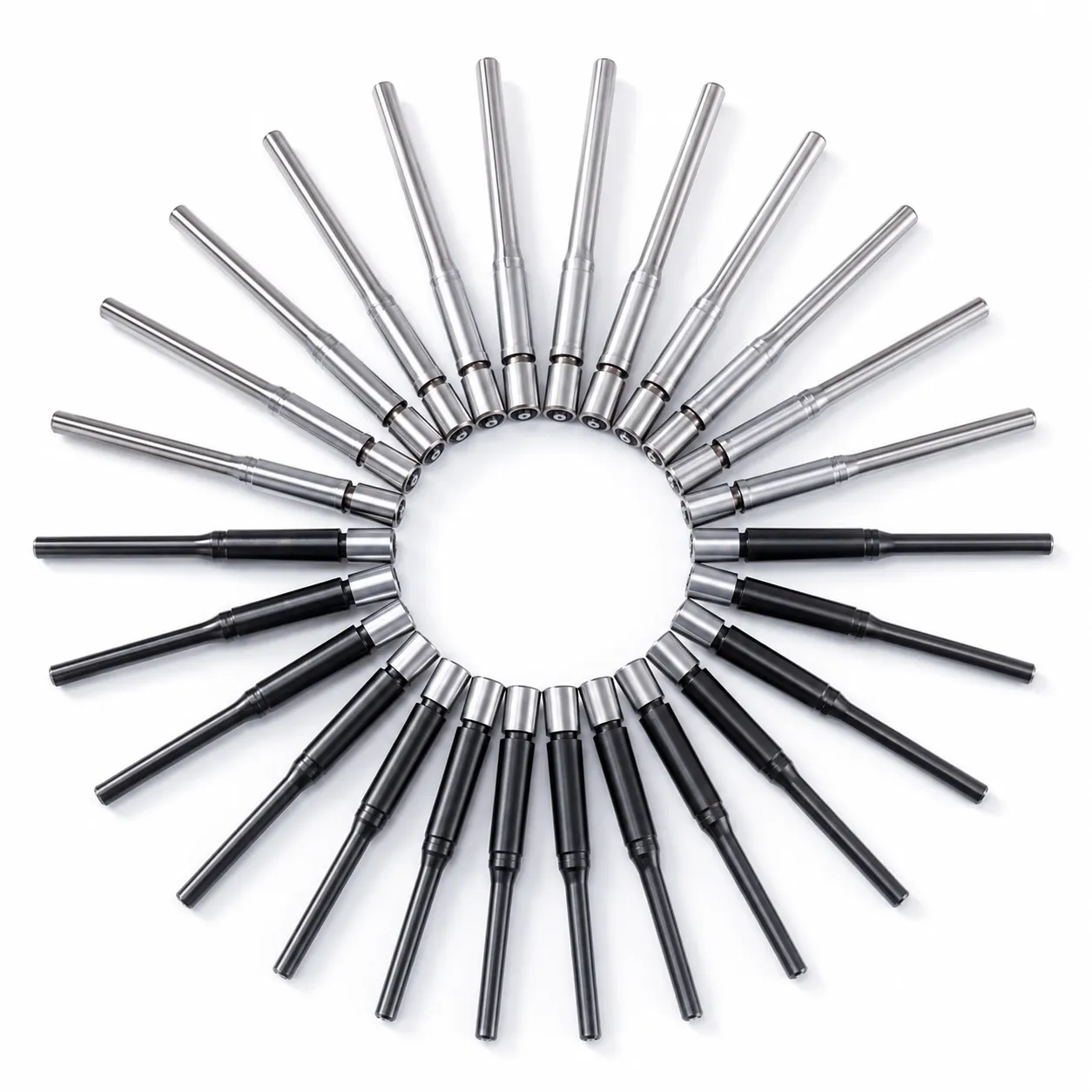
Station 3 is the simplest of the three stations mechanically — but it is the station where several IBM quality outcomes become visible and where subtle process problems manifest as container defects.
Stripping Force Balance
The finished container must slide off the core rod under the stripping tool’s force. Two competing forces: the HDPE’s thermal shrink grip on the core rod (increases with greater cooling → higher stripping force needed) versus the HDPE’s stiffness at the stripping temperature (lower temperature → stiffer container → stripping tool engagement must be precise). Korea Ever-Power calibrates stripping tool engagement depth and stripping speed per mould set in the pre-delivery trial to ensure clean stripping without container distortion at the shoulder zone.
Container Base Geometry
IBM containers have an injection gate point at the container base interior — a small vestige at the blow air exit point on the core rod tip, transferred to the container base during injection. This gate vestige is on the container base interior and does not affect base flatness, appearance or function. IBM containers have no base weld line, no flash trim seam and no external parting mark at the base — unlike EBM containers where the base pinch weld is a structural and appearance feature that Korean premium brands reject for body wash, honey and cosmetic containers.
Output Quality Check
At Station 3 output, Korean production specifications typically require: (1) inline weight check — container weight within ±3% of nominal per cavity, confirming shot weight consistency and detecting short shots or over-pack; (2) neck OD check — statistical sampling of neck OD every 500 cycles per cavity using go/no-go gauges; (3) visual inspection — trained operator inspection at 500–1,000 lux for surface defects, short fill, base contamination. For pharmaceutical IBM, 100% cavity identification and weight sorting is standard production protocol.
SECTION 05
The Core Rod — IBM’s Central Component
The core rod is IBM’s defining component — the precision steel pin that performs four simultaneous functions throughout the 3-station process, enabling IBM’s quality characteristics that no other blow molding process achieves. Every IBM quality advantage traces back to the core rod’s role.
FUNCTION 01
FUNCTION 02
FUNCTION 03
FUNCTION 04
Core rod material: H13 tool steel (HRC 44–50), hard chrome plated (HV 900+, 15–25 μm thickness) for wear resistance and HDPE release. Surface Ra ≤ 0.10 μm on the body zone. Dimensional tolerance: ±0.01 mm OD along the full functional length. Replace when surface Ra exceeds 0.20 μm or OD deviates beyond ±0.03 mm — typically every 2–3 million cycles for pharmaceutical applications, 5–8 million for household/personal care.
SECTION 06
IBM Cycle Time Engineering
IBM cycle time determines the machine’s output rate and therefore the annual production capacity per machine and mould set. Total cycle time is the sum of all station activities — but because all three stations operate simultaneously, the cycle time equals the slowest station’s duration, not the sum of all three. The bottleneck station governs the cycle time.
CYCLE TIME BREAKDOWN · 10ml PHARMA vs 300ml SHAMPOO COMPARISON
10 ml HDPE Pharma (20 cav, ZQ80) — 4.0 s
300 ml HDPE Shampoo (6 cav, ZQ110) — 5.0 s
The blow dwell time (the time the container remains pressed against the blow mould cavity wall for cooling) is the bottleneck station in almost all IBM formats — it is determined by the container’s wall thickness and the blow mould temperature. Thicker wall (larger format, heavier container) requires longer blow dwell to solidify adequately before stripping. This is why larger containers (300–500 ml) have longer cycle times than smaller containers (10–60 ml) — a relationship covered quantitatively in the cavity count guide.
SECTION 07
How IBM Achieves Zero Flash and ±0.05 mm Neck Precision
Two of IBM’s most commercially important quality characteristics — zero base flash and ±0.05 mm neck OD precision — are direct consequences of the 3-station architecture rather than of manufacturing care or tooling quality. They are structurally inherent to the IBM process, which is why EBM cannot achieve either characteristic regardless of process optimisation.
Structural basis, not process control
IBM: The preform is formed by injecting HDPE into a closed mould around a core rod — no excess material, no pinch point, no trim. The container base is formed by the core rod tip during injection (the base is the solid end of the preform tube). There is no base parting line because the preform base was never a mould split — it was the core rod tip zone. Result: zero flash, zero trim operation, no flash contamination risk.
EBM: An extruded parison (an open-ended tube) is pinched closed at its bottom end by the blow mould closing, creating a base pinch weld and excess material (flash) that must be trimmed. The pinch weld is structurally weaker than the container body wall and the trim flash must be removed in a secondary operation. These are inherent consequences of the EBM parison-pinch architecture — they cannot be eliminated by process optimisation.
Physical isolation, not dimensional control
IBM: The neck is formed in the injection mould’s neck insert (±0.01 mm CNC tolerance) during Station 1. Throughout Station 2 (blow), the core rod physically occupies the neck bore — blow pressure is mechanically isolated from the neck zone. The neck OD when stripped at Station 3 is the same as the neck OD as-injected at Station 1: ±0.05 mm. No process in Stations 2 or 3 can change the neck dimension because no process force reaches the neck zone.
EBM: The EBM neck is formed by blow air pressure acting on a hot parison tube from inside — the blow pressure simultaneously shapes the body and the neck, with no mechanical constraint separating them. Blow pressure variability (0.5–2.0 MPa cycle-to-cycle variation) directly translates to neck OD variability of ±0.15–0.25 mm. This inherent coupling between blow pressure and neck geometry cannot be broken in EBM without secondary neck finishing operations.
SECTION 08
ZQ Series Machine Architecture
| ZQ MODEL | CLAMPING FORCE | TURRET DIAMETER | MAX CAVITIES (10ml) | PRIMARY APPLICATION |
|---|---|---|---|---|
| EP-ZQ40 | 400 KN | Compact | 9 | Pharma entry, food specialty, cosmetic small format, startup IBM |
| EP-ZQ60 | 600 KN | Mid | 14 | Food condiment, mid-scale pharma, household chemical, cosmetic mid-format |
| EP-ZQ80 ★ | 800 KN | Standard | 20 | Korean pharma national brand, household chemical OEM, food/personal care at scale |
| EP-ZQ110 | 1,100 KN | Large | 24 | Hair care premium, large pharmaceutical OEM, major food brand condiment |
| EP-ZQ135 | 1,350 KN | Full | 30 | National supply-scale pharmaceutical, major Korean FMCG at highest volumes |
★ ZQ80 is the Korean IBM production benchmark — 800 KN clamping force at 20 cavities (10 ml) covers the widest range of Korean pharmaceutical, household and personal care IBM applications in a single machine model.
PROCESS FAQ
IBM Process Engineering — Questions
Why does IBM use a rotating turret rather than a linear transfer system between stations?
The rotating turret is IBM’s defining mechanical architecture choice — and it is the reason IBM machines are compact, mechanically simple and dimensionally consistent. The turret carries all three sets of core rods in a single rigid plate, rotating 120° between stations with all core rods moving exactly the same angular distance simultaneously. This means all core rods are simultaneously at all three stations at all times — no core rod is idle or in transit. By contrast, a linear transfer system would require core rods to queue, transfer and wait, introducing: additional machine length (2–3× footprint versus turret IBM); transfer mechanism wear points that introduce positional variation; and idle time during which core rods cool between stations, requiring reheating conditioning zones. The turret architecture also means that every core rod in the machine follows exactly the same angular path with the same rotation timing — a geometric consistency that contributes to IBM’s cavity-to-cavity uniformity. The turret’s single central rotation axis also allows the injection unit, blow station and stripping station to be permanently oriented relative to each other at fixed 120° angles, eliminating the need for adjustable alignment mechanisms that would introduce positional drift over production life.
What causes IBM container surface defects — and which station produces each type?
IBM container surface defects are station-specific, which allows systematic root cause identification during production troubleshooting. Station 1 defects (on the preform / container neck zone): sink marks at the neck wall junction → insufficient hold pressure or hold time; silver streaks at the neck gate → HDPE moisture above 0.02% (pre-drying required); short shot at the neck thread → gate or hot runner blockage; flash at the neck OD parting line → injection mould wear at the neck insert parting line (requires neck insert replacement or lapping). Station 2 defects (on the container body): whitening / haze lines on the body wall → preform temperature too low at blow entry (Station 1 cooling too fast — reduce cooling time or increase cooling water temperature); incomplete body inflation → blow pressure too low or preform temperature too cold; body wall thinning at shoulder → preform wall distribution insufficient at shoulder zone (preform design change needed); blow mould surface marks → blow mould cavity damage (inspect blow mould and polish if scratched). Station 3 defects (container base / shoulder zone): shoulder deformation → stripping force too high or container too hot at stripping (extend blow dwell or lower blow mould temperature); base drag marks → core rod tip scratch (inspect and polish or replace core rod); base haze / crystallisation marks → container too cold at stripping (reduce blow dwell slightly). The station-specific nature of IBM defects is a significant troubleshooting advantage — a defect located precisely on the neck points to Station 1, a defect on the body points to Station 2, and a defect on the base or shoulder points to Station 3, immediately narrowing the root cause investigation scope.
How does changing mould temperature affect the IBM container quality vs cycle time trade-off?
Mould temperature in IBM is a critical process variable that creates a direct quality-versus-cycle-time trade-off, and understanding this trade-off is essential for IBM production optimisation. Injection mould temperature (Station 1): lower temperature (12–18°C) → faster preform solidification → shorter Station 1 cooling time → potentially shorter cycle time. But too-low injection mould temperature produces: insufficient preform surface replication (reducing gloss in cosmetic applications), higher residual stress in the preform neck zone (potentially reducing neck OD dimensional stability under fill forces), and inadequate transfer temperature at Station 2 entry (preform too cold for clean inflation). Optimal injection mould temperature is therefore a balance between cooling speed and preform quality — pharmaceutical IBM typically uses 14–18°C, cosmetic ABS IBM uses 55–70°C (prioritising surface quality over cycle speed). Blow mould temperature (Station 2): lower blow mould temperature → faster container body solidification → shorter blow dwell required → shorter cycle time. But too-low blow mould temperature produces: surface whitening on the container body (HDPE crystallises too rapidly, producing visible spherulites on the surface); poor surface texture replication (embossed details are less sharp at cold mould temperatures because the HDPE surface solidifies before fully contacting the mould cavity wall); and base deformation at stripping (container is too stiff and brittle when stripped too cold, producing micro-cracks at the base corner zone). For each application (pharmaceutical, food, personal care, cosmetic) and each HDPE grade, Korea Ever-Power establishes the optimal mould temperature range during the pre-delivery production trial — the range that minimises cycle time while maintaining all container quality specifications — and records this as the qualified process parameter range in the production trial report.
What is the IBM preform, and how does its design determine the finished container wall distribution?
The IBM preform is a thick-walled hollow tube produced at Station 1 — it has the container’s finished neck (thread, features, sealing land) already formed at its top end, and an unconstrained body tube below the neck that will be inflated at Station 2 to become the container body. The preform design — specifically its body wall thickness as a function of axial position from neck to base — determines how the HDPE material distributes into the finished container body during blow inflation. This is the fundamental IBM wall engineering parameter. In a cylindrical container, a uniform-wall preform (same wall thickness from shoulder to base) produces a container body wall that is approximately uniform from shoulder to base — the blow ratio (body diameter ÷ preform OD) is constant along the container height, so the HDPE stretches the same amount at every axial position. In a non-cylindrical container — oval cross-section, waisted body, wide shoulder with narrow base, or shampoo oval — the blow ratio varies with axial position. The shoulder zone (where the body transitions from the narrow neck diameter to the maximum body diameter) has the highest blow ratio and therefore the highest wall thinning risk. Korea Ever-Power engineers the preform wall thickness profile for each IBM container design using blow ratio calculation: at each axial position, preform wall thickness × preform circumference = finished container wall thickness × finished container circumference (conservation of mass). Where the finished container circumference is largest relative to the preform circumference, the preform wall at that zone must be thickest to compensate — this is the shoulder-zone wall bias used in shampoo and condiment IBM preform design. The preform wall profile is CNC-machined into the injection mould core cavity to ±0.02 mm accuracy, producing the specified wall distribution in the finished IBM container.
Can IBM produce containers with handles, and what are the design constraints?
IBM cannot produce hollow integral handles — the blow mould architecture that eliminates flash (no pinch weld) also eliminates the ability to form a hollow loop handle because hollow handle formation in blow molding requires a parison to be pinched and welded across the handle opening during blow mould closure. Since IBM has no parison pinch, it has no handle pinch — integral hollow handles are EBM’s exclusive capability. IBM containers can, however, incorporate several forms of non-hollow handle features: (1) solid grip zones — the IBM blow mould can incorporate ergonomic grip recesses (indentations) on the container body sides; the HDPE body inflates into these recesses, creating grip features that function like handles for hand-holding the bottle during dispensing, without being hollow through-handles; (2) solid textured grip zones — circumferential ribs, dimples or diamond-knurl patterns on the IBM blow mould cavity transfer to the container body surface, providing grip without changing the body’s cross-sectional profile; (3) external handle clips — a separate injection-moulded handle component clips onto the IBM bottle’s neck or body features post-production, commonly used on Korean large-format (500 ml+) household chemical IBM containers. For Korean applications requiring true through-handles (gallon-size Korean laundry detergent, Korean bleach large format), EBM is the correct process — IBM’s handle limitation is structural to its process architecture and cannot be overcome by tooling or parameter changes.
What is the maximum container volume IBM can produce and what limits it?
The practical maximum IBM container volume on Korea Ever-Power’s ZQ135 (1,350 KN) is approximately 1,000–1,500 ml at 1–2 cavities for non-pharmaceutical applications, and approximately 500 ml at 4 cavities for pharmaceutical applications. The theoretical IBM volume limit is set by the intersection of three constraints that all tighten as volume increases: clamping force, platen size and shot weight. As container volume increases, the preform body becomes longer and wider — increasing both the per-cavity injection clamping force requirement (proportional to projected area × injection pressure) and the per-cavity platen footprint (proportional to body cross-sectional area). Shot weight constraint: a 1,000 ml HDPE IBM container at 1.0 mm average wall weight is approximately 55–65 g per container — a 2-cavity 1,000 ml mould on ZQ135 requires a shot weight of 110–130 g per cycle, which approaches the ZQ135’s shot weight limit and leaves no margin for mould and hot runner system hold-up. In practice, Korean IBM applications above 500 ml are uncommon because: (1) Korean food and personal care brands at 500 ml+ typically specify EBM (with handles, for large format detergent and rinse containers where handled bottles are preferred); (2) Korean pharmaceutical containers are almost never above 250 ml in IBM; (3) Korean cosmetic IBM is not specified above 500 ml. The commercial IBM volume optimum — the volume range where IBM’s quality advantages over EBM are most valuable and its production economics are most competitive — is 10–500 ml, which is the primary ZQ series design target range.
IBM PROCESS CONSULTATION · KOREA EVER-POWER
Starting an IBM Container Production Project?
Korea Ever-Power’s applications engineering team provides IBM process consultation — container design review, preform wall engineering, cavity count calculation and ZQ series machine selection — for all Korean pharmaceutical, food, household and personal care IBM projects.